

Anti-glare device and method for automobiles
a technology for automobiles and anti-glare devices, which is applied in the direction of anti-glare equipment, vehicle components, transportation and packaging, etc., can solve the problems of rigid parts, difficult and expensive manufacturing, installation, and severe obstructing the vision of drivers
- Summary
- Abstract
- Description
- Claims
- Application Information
AI Technical Summary
Benefits of technology
Problems solved by technology
Method used
Image

Examples
first embodiment
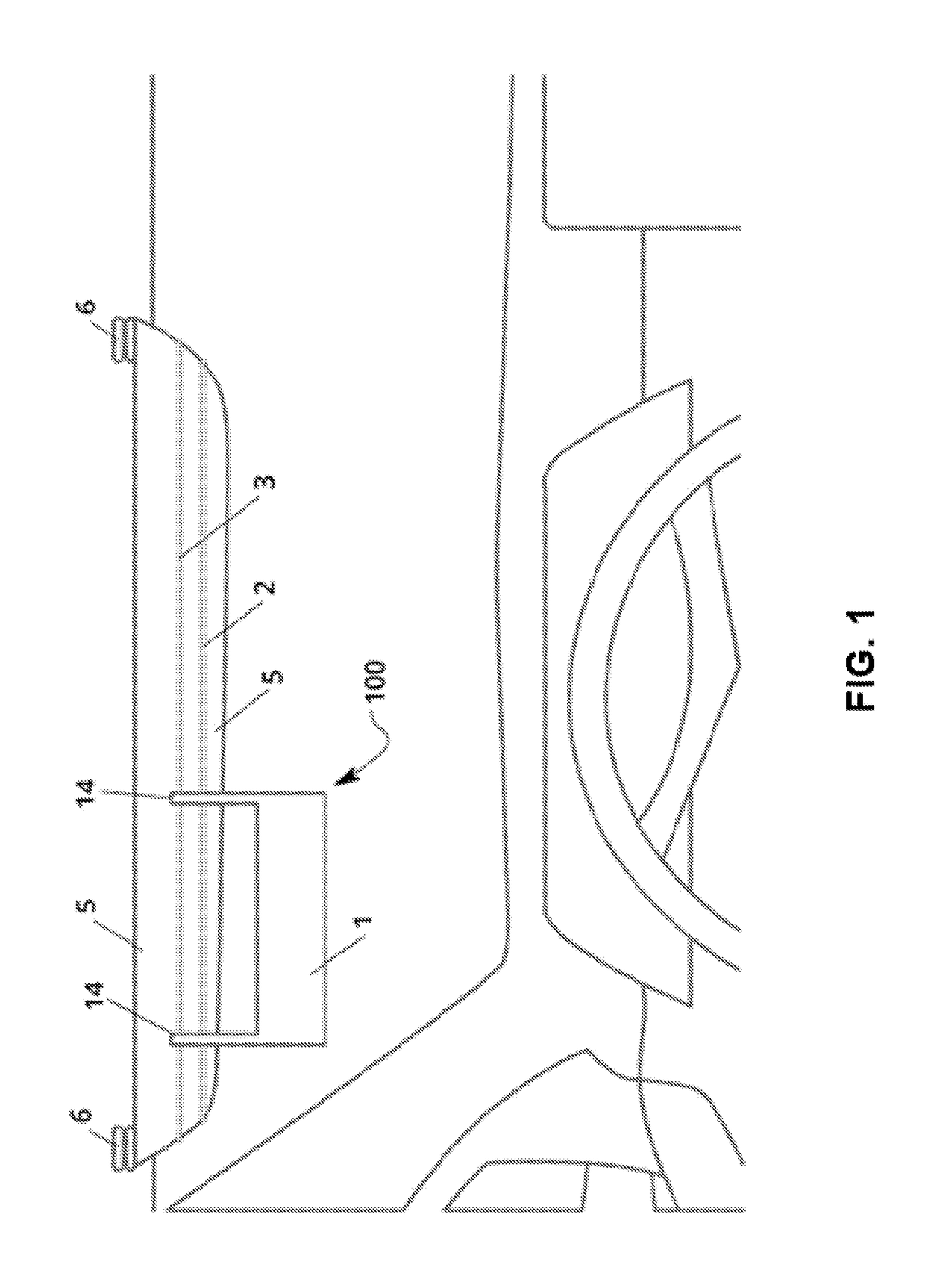
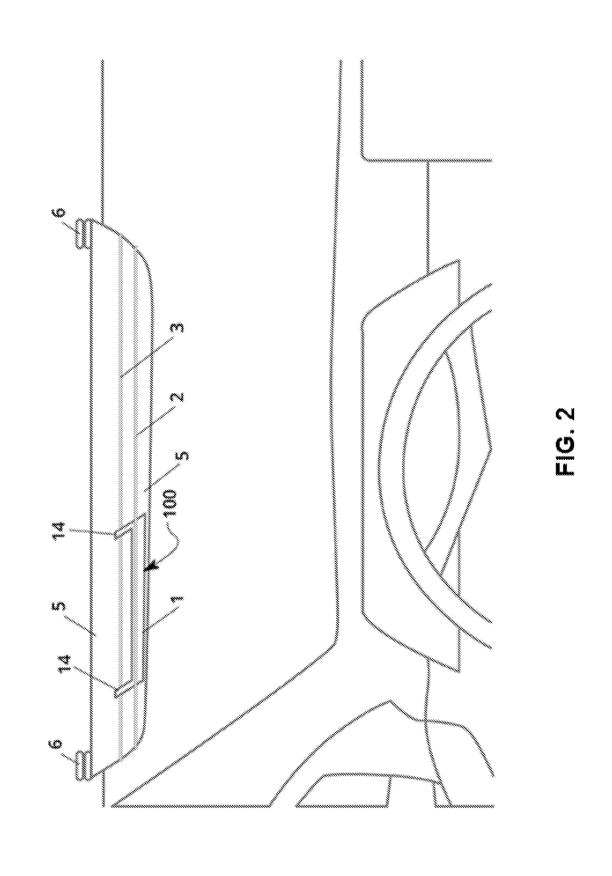
[0030]FIG. 1 shows an device 100 according to the present invention.
[0031]Here, the anti-glare device 100 is installed on a sun visor 5 of an automobile. In a typical automobile, the sun visor 5 is attached to the ceiling of the automobile via one or more visor attachment mechanisms 6, which typically comprise hinges and / or clips for tilting the sun visor 5 forward, backward, left and / or right. In the illustrated example, the visor attachment mechanisms 6 attach to the top edge of the sun visor 5.
[0032]In the illustrated example, the anti-glare device 100 includes an anti-glare panel 1, which is a strip of tinted, transparent film, and an attachment mechanism comprising a primary elastic member 3 (e.g., an elastic string or an elastic band) and a secondary elastic member 2. In general, the attachment mechanism secures the anti-glare panel 1 to the sun visor 5, and the anti-glare panel 1 reduces the glare by attenuating and / or filtering the light traveling from the source of glare th...
second embodiment
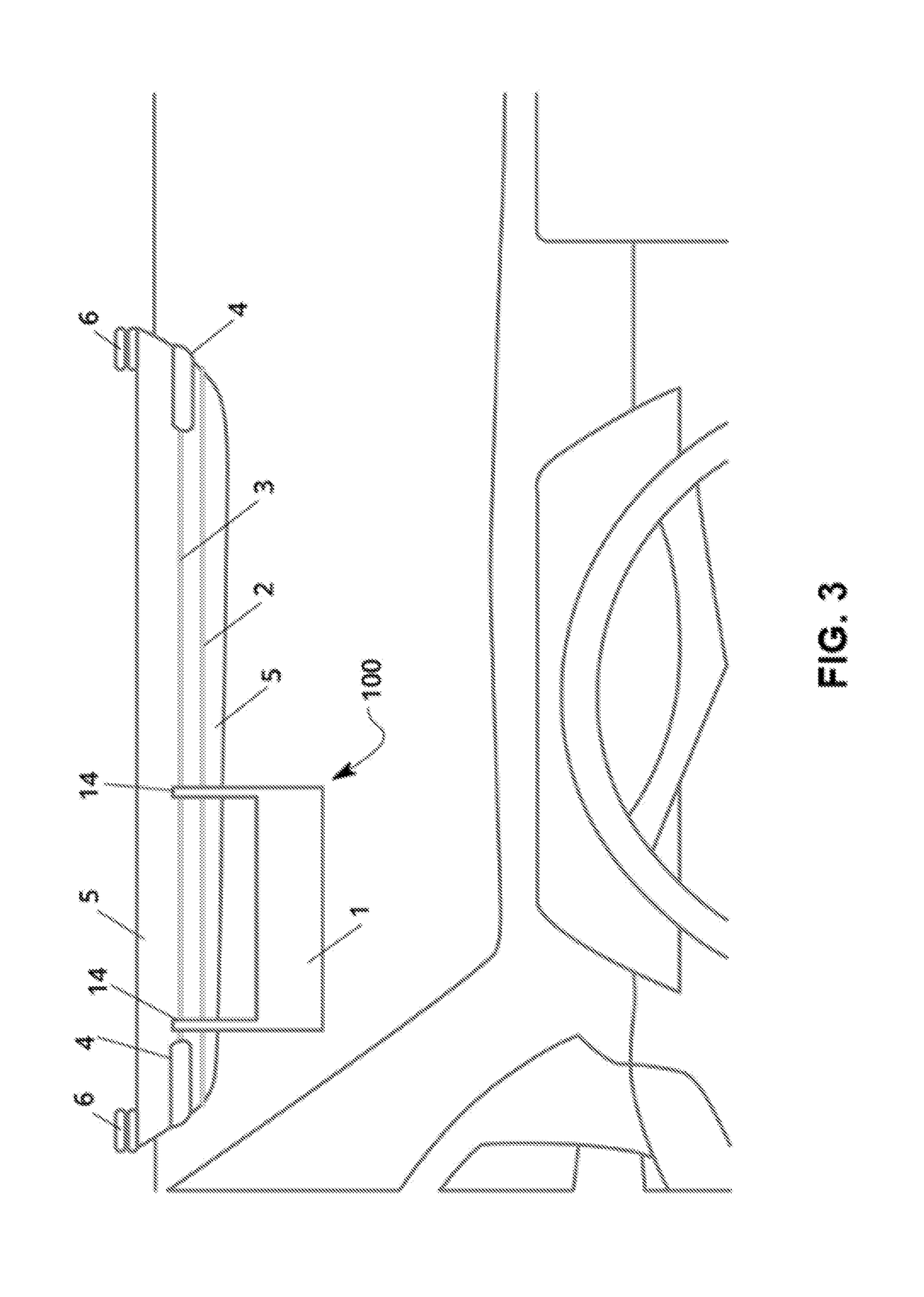
[0045]FIG. 3 illustrates an example of the anti-glare device 100. In this example, the attachment mechanism further comprises two U-shaped clips 4. Instead of joining together to form a ring, each end of the primary elastic member 3 attaches to one of the U-shaped clips 4. The U-shaped clips then attach to the left and right side edges of the sun visor 5, securing the anti-glare device 100 in place.
[0046]FIG. 4 illustrates an example of the second embodiment of the anti-glare device 100 comprising the U-shaped clips 4, wherein the anti-glare panel 1 is secured in an inactive position by the secondary elastic member 2.
[0047]FIG. 5 is an image of the first embodiment of the anti-glare device 100. In the image, the device is not installed. Depicted are the anti-glare panel 1, the attachment arms 14 and the primary elastic member 3.
third embodiment
[0048]FIG. 6 is an image of the anti-glare device 100. In the depicted embodiment, the horizontal length of the anti-glare panel 1 decreases over the vertical width of the anti-glare panel 1, forming a recess 15 at the bottom right corner of the panel. Now the anti-glare panel 1 can be positioned such that light from the center of the road does not pass through the anti-glare panel 1 and thus reaches the driver's eye without being filtered or attenuated. In this way, the recess 15 allows for natural visibility of the center line and / or lane markings of the road by not obscuring or reducing the intensity of light coming from the region of the driver's visual field most likely to contain the center line and / or lane markings.
PUM
 Abstract
Description
Claims
Application Information