Gas-measuring device

a technology of gas-measuring device and gas-measuring chamber, which is applied in the construction details of gas analyzers, instruments, scanning probe techniques, etc., can solve the problems of large number of toxic substances and jeopardize the health of persons who are present, and achieves a compact construction mode, rapid response characteristic, and long service life

Inactive Publication Date: 2019-01-29
DRAGER SAFETY
View PDF37 Cites 23 Cited by
  • Summary
  • Abstract
  • Description
  • Claims
  • Application Information

AI Technical Summary

Benefits of technology

[0014]The basic idea of the present invention is that an especially early and reliable gas warning can be achieved if the sensor unit of a gas-measuring device is regenerated especially thoroughly and rapidly. This is accomplished according to the present invention by the gas sensor not only being heated, but also evacuated. These two desorption processes (thermal desorption and vacuum desorption) take place essentially simultaneously. The atoms or molecules of the analyte leave the surface of the receptor solid during the desorption of the receptor of the gas sensor, so that the receptor is “cleaned” for the next measurement. The desorption is carried out according to the present invention by simultaneous heating and evacuation of the receptor especially rapidly and thoroughly in order to prepare the gas sensor for the next measuring operation. Significantly shorter response and regeneration times can thus be attained for adsorption-based sensors.
[0015]The measuring channel is configured to form a pressure-tight cavity if both the gas inlet and the gas outlet are likewise closed in a pressure-tight manner. The measuring channel may have a round, square, oblong but also bent shape. Different geometric shapes of the measuring channel make it possible to advantageously adapt the sensor unit to the spatial conditions. Thus, an especially small type of construction can be obtained, for example, with a bent measuring channel.
[0018]The pump unit is configured to evacuate the measuring channel. The gas molecules detected in a current measurement process are desorbed from the receptor of the gas sensor and the receptor is prepared for the next measurement process due to the evacuation of the measuring channel and hence of the gas sensor. The pump unit may also be operated to draw gas into the measuring channel or to pump gas into same. The entry of gas into the measuring channel can thus be expedited, which in turn makes possible a more rapid measurement. The pump unit is preferably arranged at the gas outlet and is configured to evacuate the measuring channel when the gas inlet is closed. Evacuation of the measuring channel is achieved especially rapidly hereby.
[0023]In one embodiment, the gas sensor is based on a capacitively-controlled field effect transistor sensor (CCFET). An especially compact mode of construction of the sensor unit can be achieved due to the use of such a gas sensor. Further, CCFETs can be manufactured cost-effectively due to mass production; they have high sensitivity in the ppm range and long service life.
[0025]In one embodiment, the gas sensor is a Surface-Acoustic Wave Sensor (SAW). Surface waves propagate in a SAW gas sensor on a piezo crystal and are converted into voltage fluctuations. If the analyte is bound to a material arranged on the piezo crystal, the weight of the piezo crystal and hence the wave characteristic (travel time or velocity of propagation, amplitude, frequency) of the surface wave will change on the piezo crystal. This change is reflected in the voltage fluctuations, as a result of which the analyte is detected. The SAW gas sensors advantageously also have a rapid response characteristic and long service life.
[0026]The above-mentioned gas sensors have advantages in the sense that they are very compact, which makes, in turn, possible a more compact mode of construction of the sensor unit and hence of the gas-measuring device. Further, their energy consumption is low, so that the sensor unit can be operated over a longer period of time. Their response times for the measurement process and the temperature control, i.e., the heating as well as the subsequent cooling, are also relatively short, so that rapid measurement and preparation for the next measurement are made possible. This is essential for guaranteeing early warning about a gas that is present.

Problems solved by technology

A very large number of toxic substances, which jeopardize the health of persons who are present, may occur in the gas phase of the ambient air in such fields of application.

Method used


Image

  • Gas-measuring device
  • Gas-measuring device
  • Gas-measuring device

Examples


Embodiment Construction

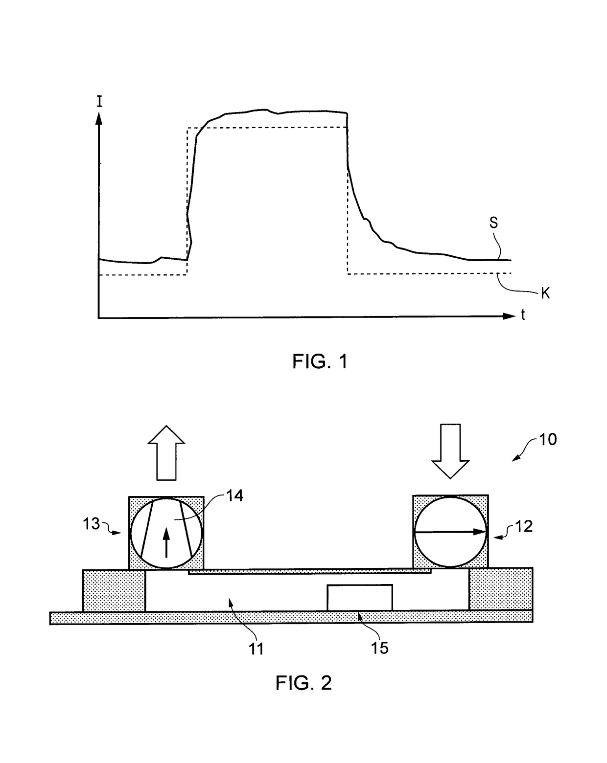
[0050]Referring to the drawings, FIG. 2 shows a schematic view of the configuration of a sensor unit 10. The sensor unit 10 is configured for the detection of a gas and has: A pressure-tight measuring channel 11, a gas inlet 12 for introducing (indicated by an arrow) the gas into the measuring channel 11, a gas outlet 13 for removing (likewise indicated by an arrow) the gas from the measuring channel 11, and a pump unit 14 for evacuating the measuring channel 11.

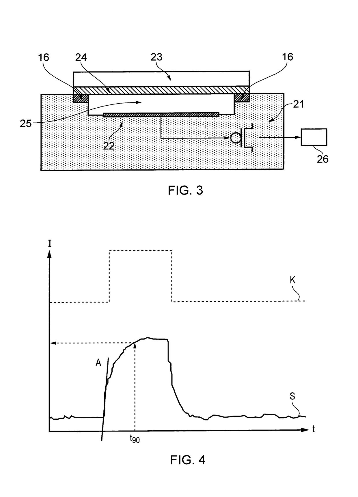
[0051]The measuring channel 11 has a gas sensor 15 for detecting the gas and a heating unit 16 for heating the gas sensor 15. The sensor unit 10 is configured to be operated in a measuring mode and a regeneration mode. The measuring channel 11 is evacuated and the gas sensor 15 is heated in the regeneration mode, as a result of which rapid and thorough desorption is achieved.

[0052]The gas sensor is, for example, a CCFET (as is shown in FIG. 3), which is integrated in the pressure-tight channel 11. This measuring channel 11 m...


PUM

PropertyMeasurementUnit
temperaturesaaaaaaaaaa
time periodaaaaaaaaaa
temperatureaaaaaaaaaa

Abstract

A sensor unit (10) for detecting a gas is configured with a pressure-tight measuring channel (11), with a gas inlet (12) for introducing the gas into the measuring channel, with a gas outlet (13) for removing the gas from the measuring channel, and with a pump unit (14) for evacuating the measuring channel. The measuring channel has a gas sensor (15) for detecting the gas and a heating unit (16) for heating the gas sensor. The sensor unit (10) is configured to be operated in a measuring mode and in a regeneration mode. The measuring channel (11) is evacuated and the gas sensor (15) is heated in the regeneration mode.

Description

CROSS REFERENCE TO RELATED APPLICATIONS[0001]This application is a United States National Phase Application of International Application PCT / EP2015 / 000028 filed Jan. 9, 2015 and claims the benefit of priority under 35 U.S.C. § 119 of German Application 10 2014 000 343.4 filed Jan. 11, 2014, the entire contents of which are incorporated herein by reference.FIELD OF THE INVENTION[0002]The invention pertains to a sensor unit for detecting a gas, to a method for operating such a sensor unit and to a gas-measuring device with such a sensor unit.BACKGROUND OF THE INVENTION[0003]Gas-measuring devices are used to detect and to monitor gases and vapors in the ambient air of a human user. Gas-measuring devices are important, in particular, for detecting and monitoring toxic gases in an industrial environment and at the workplace. A very large number of toxic substances, which jeopardize the health of persons who are present, may occur in the gas phase of the ambient air in such fields of appl...

Claims


Application Information

Patent Timeline
Patent Type & Authority Patents(United States)
IPC IPC(8): G01N33/00G01N29/24G01Q60/24G01N27/414
CPCG01N33/0029G01N33/0009G01Q60/24G01N29/2462G01N2291/0215G01N27/4141G01N33/00
Inventor BATHER, WOLFGANGRAUPERS, BJORNLEHMANN, STEFAN
Owner DRAGER SAFETY
Why Eureka
Try Eureka