Combustion apparatus for combusting recyclable or waste material

a technology for combusting apparatuses and recyclables, applied in the field of combusting apparatuses for combusting recyclables or waste materials, can solve the problems of large waste generation burden on society and infrastructure, generating toxic and/or hazardous compounds, etc., and achieve the effect of minimal solid residue remaining

Active Publication Date: 2019-02-05
M G H RECYCLING
View PDF18 Cites 0 Cited by
  • Summary
  • Abstract
  • Description
  • Claims
  • Application Information

AI Technical Summary

Benefits of technology

[0008]The apparatus according to the invention is advantageous principally because the blower forces in large amounts of air into the apparatus therefore resulting in large amounts of oxidation of the waste or recyclable material during the combustion process. The blower also forces the materials to circulate within the chamber and this not only completely mixes the waste or recyclable material materials, but forces the heavier less combusted elements towards the inside of the chamber wall. A gradient of particle weight is set up within the apparatus, such that the light combusted material (ash / gas etc.) moves towards the axis of rotation and then out of the outlet, whereas the heavier un-combusted materials remain close to the walls of the chamber. Overall this results in an efficient combustion process at very high temperatures with minimal solid residue remaining. Due to the high temperatures created in use, most toxic and / or harmful materials which would otherwise be released from waste or recyclable materials during processing are significantly eliminated. Therefore the apparatus can be used to combust waste or recyclable materials which are otherwise hazardous to dispose of.
[0018]In use, the ignition means is switched on and the primary combustion products of the ignition means are preferably blown into the chamber via the first inlet by the air or the like from the blower. Recyclable or waste material is preferably delivered into the chamber from the source by the conveyor via the second inlet. Recyclable or waste material may also be delivered into the chamber via the second inlet, directly (i.e. poured straight in without using the conveyor). The recyclable or waste material is preferably ignited by contact with the primary combustion products of the ignition means. Preferably the source of recyclable or waste material within the first inlet and blower at the second inlet create seal to prevent combustion products escaping from those areas. The action of the air or the like from the blower within the chamber preferably forces the recyclable or waste material and / or the primary combustion products to circulate around the inside of the chamber. In a preferred embodiment, the circulation of material within the chamber is in a substantially uniform direction. The circulation of material within the inside of the chamber is preferably around the longitudinal axis of the chamber. The action of the primary combustion products on the recyclable or waste material preferably causes the recyclable or waste material to ignite and combust. Combusted material preferably exits the chamber through the outlet. Once combustion of the recyclable or waste material has begun, preferably the ignition means is switched off. Further recyclable or waste material is preferably fed into the chamber via the second inlet. In this way preferably the resultant combustion is self-sustaining.

Problems solved by technology

The generation of waste is a great burden to society and infrastructure.
The task of dealing with the vast variety of materials in an efficient manner is therefore a challenging one.
One of the main problems when handling domestic and commercial waste materials is the generation of toxic and / or hazardous compounds which originate from the materials themselves and / or residual compounds contained within the waste.
This problem is exemplified when handling waste construction industry fibre board.
During the initial processing the fibre board is particulated, thereby exposing the harmful adhesives and preservatives contained within the board products.
This is not sustainable in the long term and has environmental consequences.
Other schemes involve large scale incineration to generate electricity, but this often leads to large emissions of harmful gases.

Method used


Image

  • Combustion apparatus for combusting recyclable or waste material

Examples


Embodiment Construction

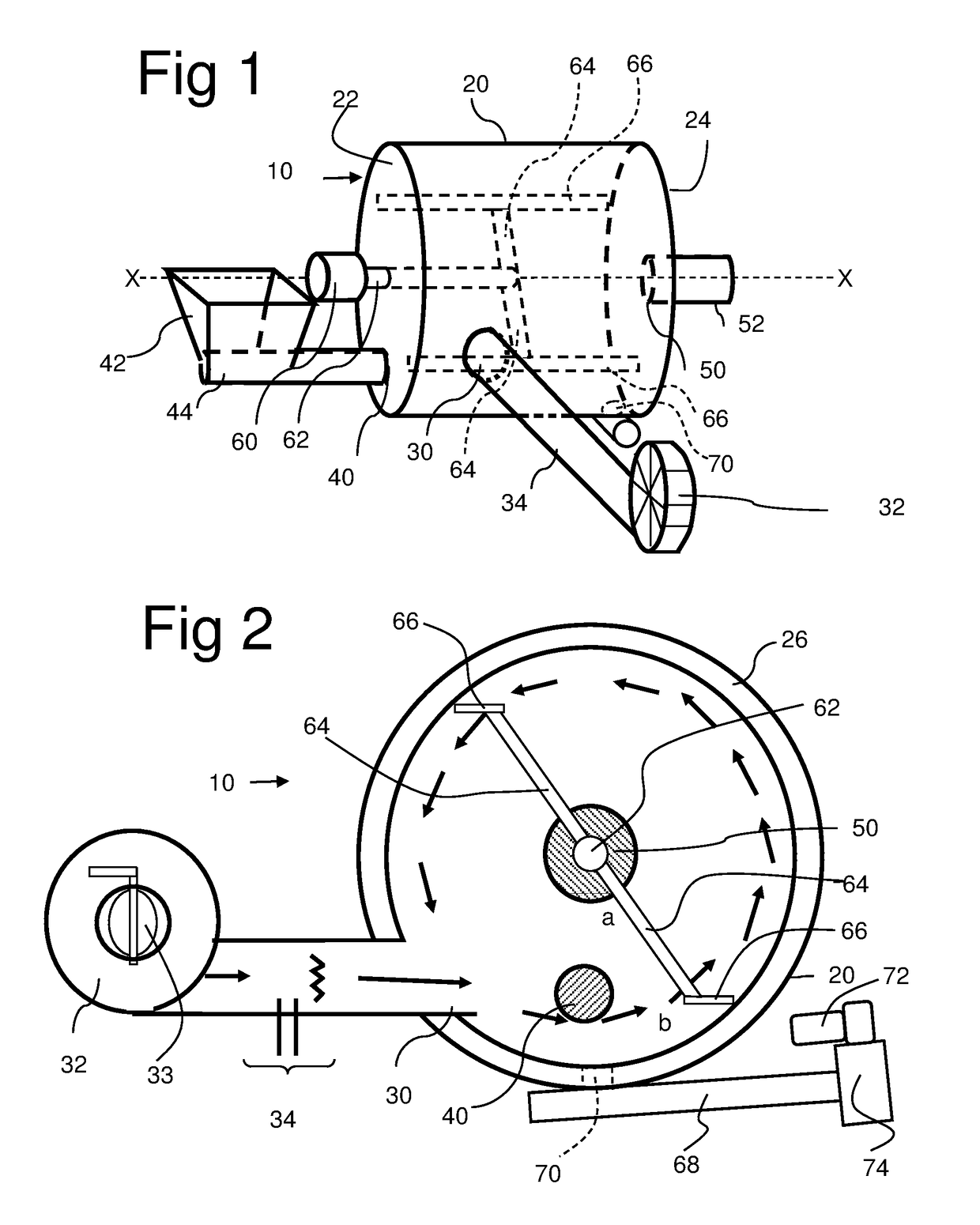
[0022]FIG. 1 shows a perspective view of the apparatus according to the invention. The apparatus is generally designated 10 and comprises a cylindrical chamber 20 which has a longitudinal central axis X-X, and a circular cross section. The chamber 20 is made of steel and the cylindrical side wall is welded to the first end wall 22, while the second end wall 24 is mounted on hinges and held closed on the end of the cylinder by bolts (not shown). In this way, the chamber can be opened up for maintenance or cleaning.

[0023]In the side wall of the chamber 20 there is a first inlet 30 which is connected to a blower 32, suitably a centrifugal fan having a rotatable vane 33 in its inlet to enable the air flow to be controlled. Between the blower 32 and the chamber 20 is an igniter 34. In the first end wall 22 there is disposed a second inlet 40 which is connected to a steel hopper 42. At the base of the hopper 42 there is an auger 44 which extends into the second inlet 40. In the second end...


PUM


Abstract

Disclosed is an apparatus for combusting recyclable or waste material. The apparatus comprises a cylindrical combustion chamber. The chamber comprises a first inlet in a side wall. The first inlet is in communication with a blower and an ignition means. The chamber also comprises a second inlet in a first end wall or a side wall. The second inlet is in communication with a source of recyclable or waste material. The chamber also comprises an outlet in a second end wall on a central axis of the chamber. The longitudinal axis of the first inlet is offset from the central axis of the chamber. In use, the blower forces the recyclable or waste material to circulate around the inside of the chamber.

Description

RELATED APPLICATIONS[0001]This application is a national phase application filed under 35 USC § 371 of PCT Application No. PCT / GB2014 / 052724 with an International filing date of Sep. 9, 2014, which claims priority to GB1315979.3, filed Sep. 9, 2013. Each of these applications is herein incorporated by reference in their entirety for all purposes.FIELD OF THE INVENTION[0002]The present invention relates to recycling and, more specifically to apparatuses for the combustion of recyclable or waste material.Background of the Invention[0003]The generation of waste is a great burden to society and infrastructure. Governments are being required to manage both domestic and commercial waste on massive scales in a manner that is sustainable over the long term. The task of dealing with the vast variety of materials in an efficient manner is therefore a challenging one.[0004]One of the main problems when handling domestic and commercial waste materials is the generation of toxic and / or hazardous...

Claims


Application Information

Patent Timeline
Patent Type & Authority Patents(United States)
IPC IPC(8): F23G5/12F23C7/00F23G5/44F23J1/00F23G7/10F23G5/46F23G5/32
CPCF23G5/12F23C7/002F23G5/32F23G5/442F23G5/46F23G7/105F23J1/00Y02E20/12F23G2203/30F23G2203/403F23G2205/121F23G2206/203F23J2700/003F23K2203/202
Inventor HARRIS, MICHAEL
Owner M G H RECYCLING
Why Eureka
Try Eureka