
Obturator, which is an integral part of the driving band, on an artillery projectile

a technology of projectiles and stabilizers, applied in the direction of projectiles, ammunition projectiles, weapons, etc., to achieve the effects of simple and uncomplicated, less prone to failure, and more robustness

Active Publication Date: 2021-06-15
RHEINMETALL WAFFE MUNITION GMBH
View PDF30 Cites 0 Cited by
  • Summary
  • Abstract
  • Description
  • Claims
  • Application Information

AI Technical Summary

Benefits of technology

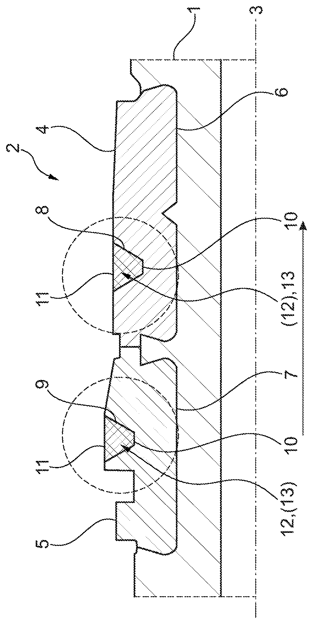
[0015]The equalizing groove can be trapezoidal in cross-section, preferably equilateral. The equalizing groove has a narrower surface pointing towards the projectile than towards the weapon barrel, which results in the trapezoidal shape. This trapezoidal shape facilitates the detachment of the obturator or sealing ring during the passage through the barrel. During the passage through the barrel, the sealing ring is pushed backwards or upwards like an O-ring out of the equalizing groove by the rearward-oriented driving band material. This action results in a sealing effect during the passage through the barrel. The obturator / sealing ring itself no longer exists as an individual part. Only one gas-flow-reducing element remains in the driving band in order to keep the pressure and the resulting velocity dispersions as low as possible. A centrifugal force-induced release after the passage through the muzzle is greatly simplified by the trapezoidal shape.
[0019]The plastic ring or sealing ring as an integral function-relevant component of the projectile is much more robust and less prone to failure. Even untrained users clearly recognize that the plastic ring does not serve as protection for the driving band, since the plastic ring is not on the driving band but is inserted into it. The driving material displaced rearwards during the passage through the barrel collides intentionally with the sealing ring material in the drive band equalizing groove, because this collision raises the dichtmetrial and additionally presses the sealing material against the barrel wall with an extreme sealing effect.
[0021]This invention is also advantageous in that it is simple and uncomplicated. The solution is robust against external influences. Remaining plastic residues on the projectile are avoided when the task as an obturator is carried out.

Problems solved by technology

This action results in a sealing effect during the passage through the barrel.

Method used


Image

  • Obturator, which is an integral part of the driving band, on an artillery projectile

Examples


Embodiment Construction

[0024]The FIGURE shows the cross-section of a spin-stabilized artillery projectile 1 in the region of a driving band 2, for example formed of brass.

[0025]In the present embodiment, the driving band 2 is made up of at least two driving band parts 4, 5—when viewed in the direction of a longitudinal axis 3 of the projectile 1.

[0026]If the driving band is a two-piece band, it usually is formed of two materials, for example brass and / or iron.

[0027]The driving band parts 4, 5 are inserted into respective grooves 6, 7 in the projectile 1. Said grooves 6, 7 preferably have a dovetail shape.

[0028]The driving band 2 can also be implemented in one piece. Welding of the driving band 2 (4, 5) is also possible.

[0029]An equalizing groove 8, 9 is introduced into each respective driving band part 4, 5. Said equalizing groove 8, 9 preferably has a trapezoidal shape in cross-section. The narrow side 10 (smaller area) is pointing towards the longitudinal axis 3. The wider side 11 (larger area) terminat...


PUM


Abstract

A spin-stabilized artillery projectile having at least one driving band and at least one obturator, wherein the driving band contains at least one compensating groove, and wherein the at least one obturator is arranged in the compensating groove of the driving band. The cross-section of the compensating groove, is preferably trapezoidal, but can also be rectangular or square. As a result, a complete detachment of the obturator is achieved and residues are avoided.

Description

[0001]This nonprovisional application is a continuation of International Application No. PCT / EP2018 / 057764, which was filed on Mar. 27, 2018, and which claims priority to German Patent Application No. 10 2017 110 426.7, which was filed in Germany on May 12, 2017, and which are both herein incorporated by reference.BACKGROUND OF THE INVENTIONField of the Invention[0002]The present invention relates to a spin stabilized projectile, in particular an artillery projectile with a driving band and with a sealing band, i.e. an obturator.Description of the Background Art[0003]An obturator has the function of a sealing ring, with which its full sealing performance is only achieved under appropriate pressure loading. The technical requirements for such a component are predetermined and binding.[0004]When passing through the barrel, due to the design conditions, a temporary form-fitting connection is made of rearward displaced driving band material with an obturator (ring). However, this form-f...

Claims


Application Information

Patent Timeline
Patent Type & Authority Patents(United States)
IPC IPC(8): F42B14/02
CPCF42B14/02F42B14/00
Inventor PAESCH, ALEXANDERDAU, OLESACKARNDT, ALFONS
Owner RHEINMETALL WAFFE MUNITION GMBH
Learn More