
Display frame with side edge engagement members

a technology of side edge engagement and display frame, which is applied in the field of display frame or holder, can solve the problems of very limited capabilities of frame types, and achieve the effect of facilitating the separation of rear panel and easy disengagement from each other

Inactive Publication Date: 2007-06-12
STRAVITZ DAVID M
View PDF17 Cites 46 Cited by
  • Summary
  • Abstract
  • Description
  • Claims
  • Application Information

AI Technical Summary

Benefits of technology

"The present invention provides new and improved display frames or holders for holding pictures or other objects. These frames have various features such as quick connect / quick disconnect mechanisms for securely retaining objects, being able to accommodate different sizes of objects, and being able to display objects in portrait and landscape modes. The frames are also designed to be easily attached and detached from a base, which makes them convenient for use. The technical effects of the invention include improved flexibility, secure holding of objects, and ease of use."

Problems solved by technology

A problem with these types of picture frames is that the size of the frame allows it to retain only the same size picture in the same orientation as the frame.
Thus, if the frame is designed for an 8×10 picture in the portrait more, it cannot be used for a smaller picture, because the picture would move around, and cannot be used for an 8×10 picture in the landscape mode, because the edges of the picture would extend beyond the edges of the frame.
Thus, these types of frames have very limited capabilities.

Method used


Image

  • Display frame with side edge engagement members
  • Display frame with side edge engagement members
  • Display frame with side edge engagement members

Examples


Embodiment Construction

[0050]As indicated hereinabove, the following detailed description is given for a picture frame, it being clear that a frame or holder for other items to be displayed is included within the scope of the present invention. Pictures are referred to for ease of description.

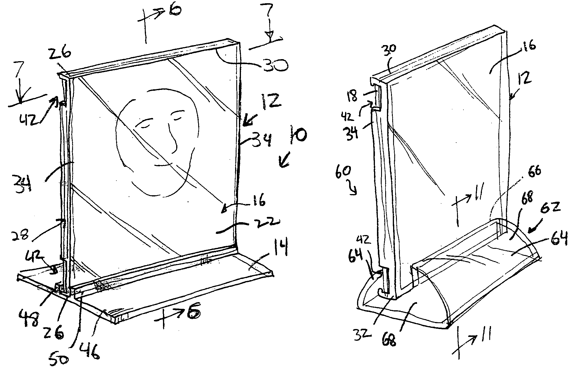
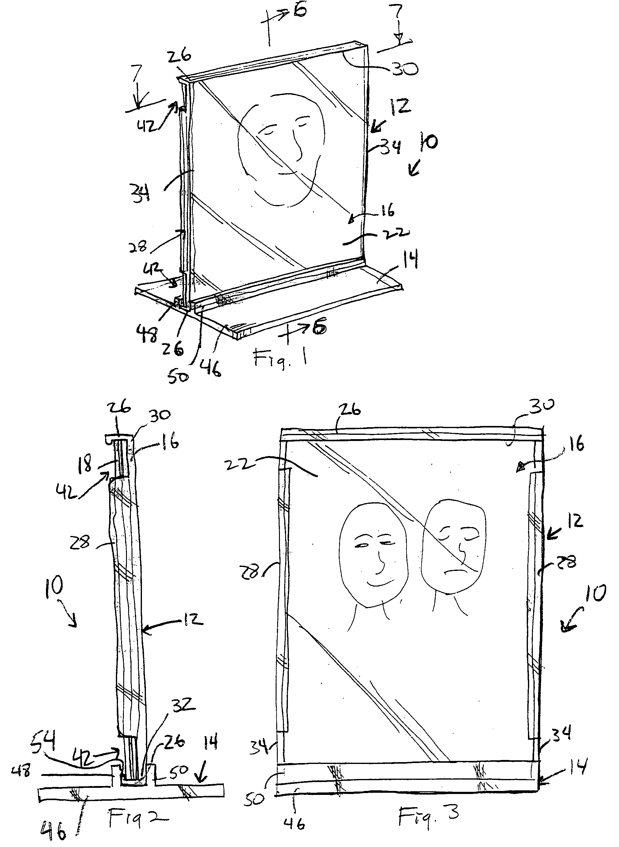
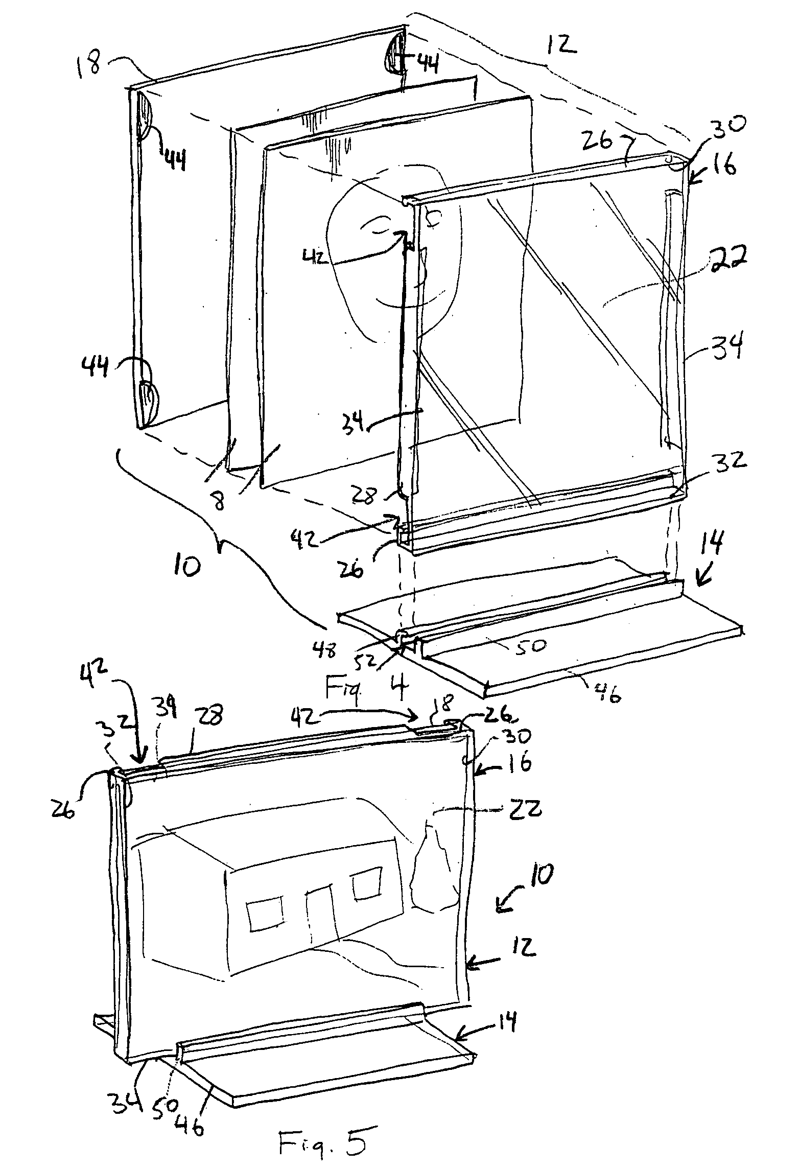
[0051]Referring first to FIGS. 1-9, a first embodiment of a frame assembly in accordance with the invention is designated generally as 10 and comprises a frame 12 and a base 14. The base 14 detachably receives the frame 12 so that the frame 12 can be removed from engagement with the base 14, e.g., to insert or replace pictures in the frame 12.

[0052]Frame 12 comprises a front panel 16 and a rear panel 18 spaced from the front panel 16 to define a space 20 therebetween capable of receiving one or more pictures 8. The front panel 16 has a transparent planar portion 22 defining a viewing window through which the pictures arranged in the space 20 between the front and rear panels 16, 18, and facing the front panel 18, wil...


PUM


Abstract

A frame assembly for pictures or other objects to be displayed includes a frame having front and rear panels defining a space therebetween for receiving objects to be displayed. A support mechanism optionally provided for supporting the frame in a substantially upright position enabling pictures to be viewed through a transparent area or window formed in one or both of the front and rear panels. The front panel includes retaining members formed along edges thereof, including at least two opposed edges, and each retaining member includes an extension portion extending rearward relative to a planar portion of the front panel and an inwardly projecting ridge formed on an inward surface of the extension portion. The rear panel is designed to fit snugly between the ridges and a rear surface of the front panel. The support mechanism may be a base separable from the frame or formed integral with the rear panel. The frame assembly may also be configured as an intermediate panel having retaining members extending forwardly and rearwardly thereof, with respective front and rear panels engageable therewith.

Description

FIELD OF THE INVENTION[0001]The present invention relates generally to picture frames and display frames or holders, and more particularly to picture / display frames or holders which include an integral mechanism for securely retaining pictures therein in order to prevent movement of the pictures or other items held in the frame or holder. The present invention also relates to picture / display frames or holders having front and rear members with quick connect / quick disconnect engagement members.BACKGROUND OF THE INVENTION[0002]The term “picture frame” is used herein to refer to a picture or display frame or holder for holding and displaying virtually any type of substantially flat item. The term “picture frame” is used for convenience of description.[0003]There are numerous different types of picture frames known in the art. Some picture frames include a holder defining a periphery of the frame, a clear front window arranged in the holder and a rear panel removably attached to the hol...

Claims


Application Information

Patent Timeline
Patent Type & Authority Patents(United States)
IPC IPC(8): G09F1/12G09F1/14
CPCG09F1/14
Inventor STRAVITZ, DAVID M.
Owner STRAVITZ DAVID M
Learn More