Vertical motion wave power generator

a technology of vertical motion and generator, which is applied in the direction of electric generator control, machines/engines, mechanical equipment, etc., can solve the problems of excessive wear of rack and pinion arrangement, insufficient durability, and inability to meet the needs of use, and achieves simple vertical frame structure and easy disengagement

Inactive Publication Date: 2010-09-07
BUSH KENNETH M +1
View PDF77 Cites 43 Cited by
  • Summary
  • Abstract
  • Description
  • Claims
  • Application Information

AI Technical Summary

Benefits of technology

[0015]An advantage of the present invention is a wave motion power generator in which the power shaft, transmission, and generator are all together on a flotation device, and they all move up and down in unison with the flotation device.
[0016]Another advantage is a wave motion power generator that uses a simple vertical frame structure attached to the ocean bottom and only a single drive chain needs to be attached to the ocean bottom.
[0017]Another advantage is a wave motion power generator that uses a single, simple power shaft to convert the up and down vertical motion of ocean waves into continuous unidirectional rotation.
[0018]Another advantage is a wave motion power generator that can be scaled up to produce power output similar to a nuclear reactor.
[0019]Another advantage is a wave motion power generator that is easy to disengage from the vertical support structure for transportation.

Problems solved by technology

However, existing devices have been too complex, or insufficiently durable, or too small to be practical or of commercial value.
The rack and pinion arrangement is subject to excessive wear.
The float and lever system, with the linkage to a stationary generator, is susceptible to damage due to the force of waves.
The flotation capacity of the float in this system is small and many units would be required to produce sufficient power.
The constant opposing motion between the floats and the generator create problems of wear and insufficient durability.
There is no capacity for a flywheel in this system which is usually required with the use of one-way clutches.
The system is inherently limited in size and many units would be required to produce sufficient power.
The cable that is wound around the drum is subject to considerable friction which causes undue wear on the cable and the drum.
The plurality of reversing gears and worm gears also causes undue friction, wear, and maintenance.
The float is relatively difficult to disengage from the frame when it is necessary to remove the float to a harbor, such as during a storm or for repair.

Method used


Image

  • Vertical motion wave power generator
  • Vertical motion wave power generator
  • Vertical motion wave power generator

Examples


Embodiment Construction

[0026]While the following description details the preferred embodiments of the present invention, it is to be understood that the invention is not limited in its application to the details of construction and arrangement of the parts illustrated in the accompanying drawings, since the invention is capable of other embodiments and of being practiced in various ways.

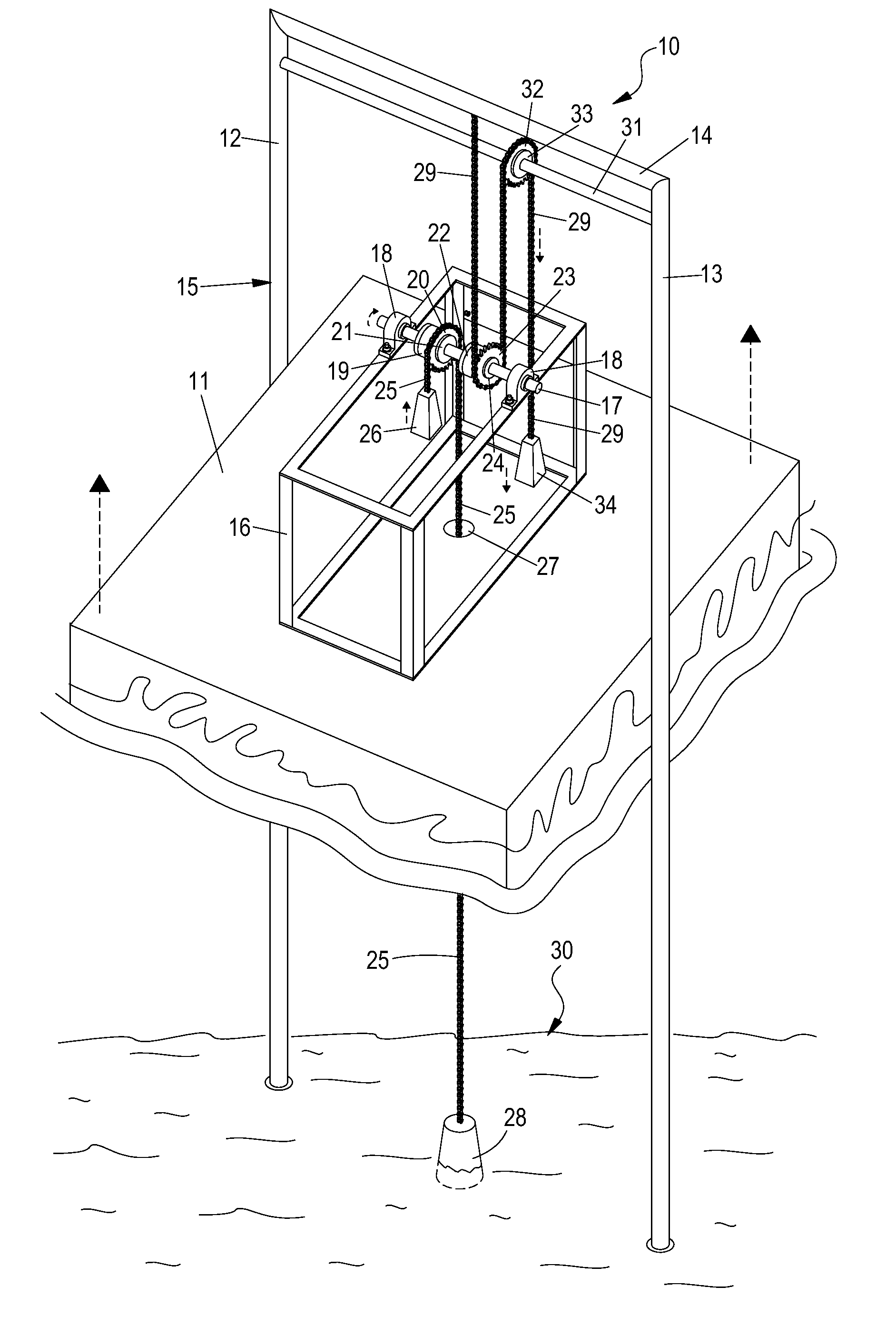
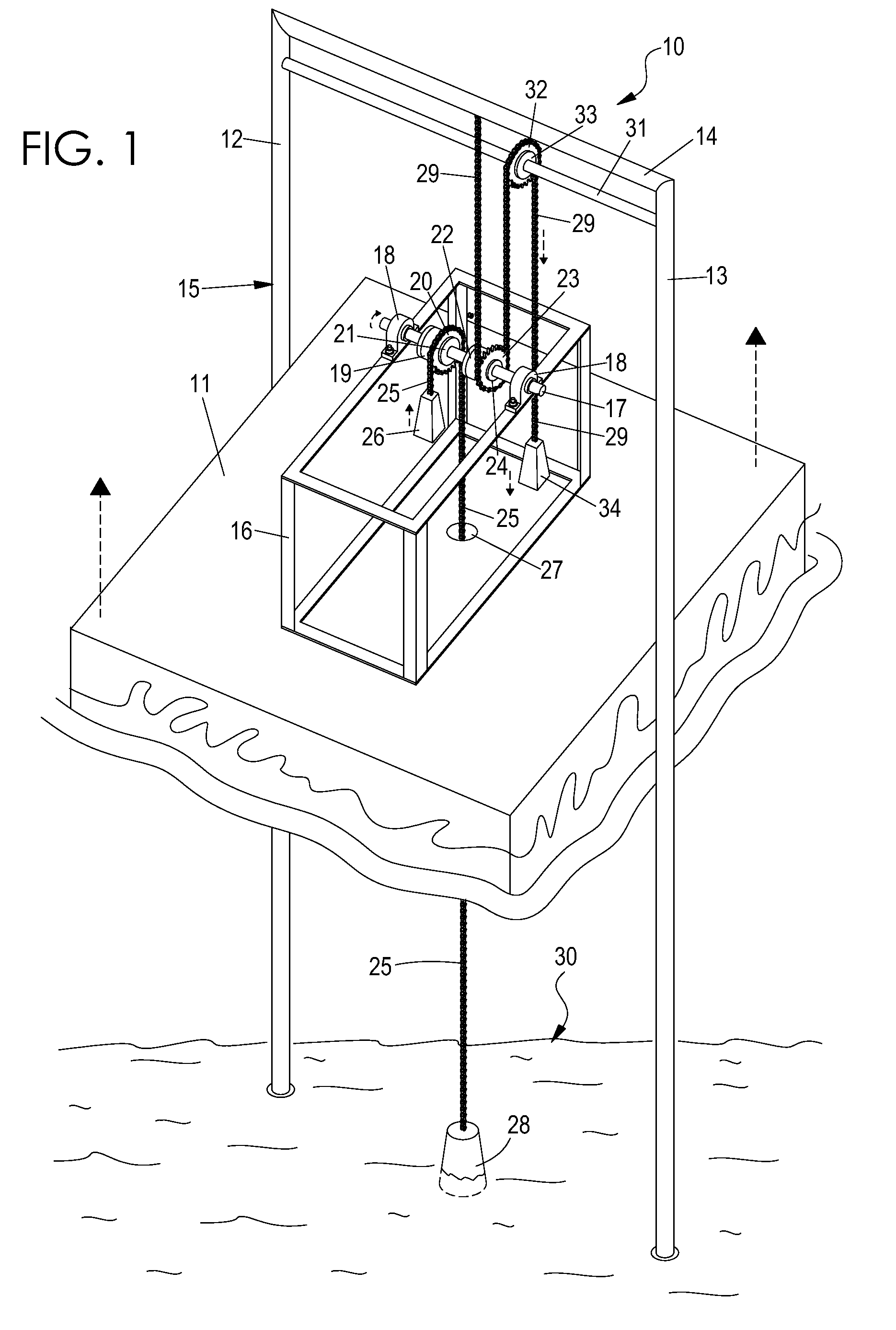
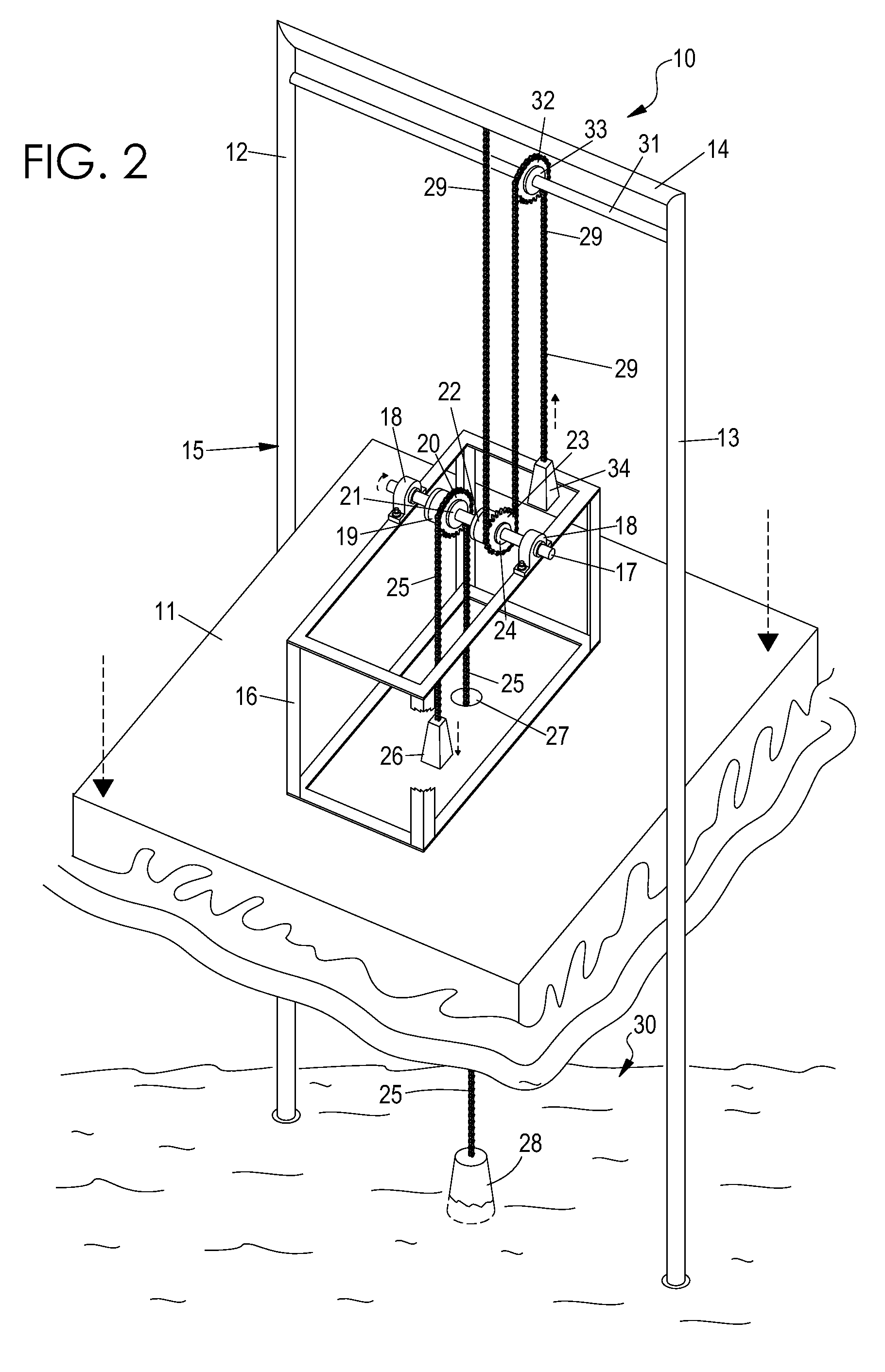
[0027]A preferred embodiment of the present invention is a floating electric wave generator system or apparatus which is attached to a flotation device. The system has a power shaft with first and second one-way clutches arranged so that both clutches rotate the power shaft in a first direction when they are rotated in this first direction, but are disengaged when rotated in a second opposite direction. The first clutch is attached to a sprocket which is driven by a chain attached to the floor of the ocean. The second clutch is attached to an overhead horizontal support which is attached to vertical supports attached to th...


PUM


Abstract

A vertical motion wave power generator having a flotation device, a vertical support structure fixed to the ocean bottom, and a single power shaft attached rotatably to the flotation device. By the use of a pair of one-way clutches the single power shaft converts the up and down motion of ocean waves into continuous unidirectional rotational force to drive an electric generator. The power shaft, transmission, and generator are all attached to the flotation device and move up and down in unison with the flotation device.

Description

CROSS-REFERENCE TO RELATED APPLICATION[0001]This application claims the benefit of U.S. Provisional Application No. 61 / 090,295 filed Aug. 20, 2008, the disclosure of which is incorporated herein in its entirety as if fully set forth below.BACKGROUND OF THE INVENTION[0002]1. Field of the Invention[0003]This invention relates generally to devices for generating power from vertical motion and, more particularly, to an apparatus for generating power from the vertical motion of ocean waves.[0004]2. Technical Background[0005]Vertical motion wave power generators for producing electricity from ocean waves are known. It has been effective to use one-way clutches to convert the up and down vertical motion of waves into unidirectional rotary motion to turn an electric generator. However, existing devices have been too complex, or insufficiently durable, or too small to be practical or of commercial value.[0006]U.S. Pat. No. 5,105,094 discloses a stationary wave generator that operates by movi...

Claims


Application Information

Patent Timeline
Patent Type & Authority Patents(United States)
IPC IPC(8): F03B13/10F03B13/12H02P9/04
CPCF03B13/1865F05B2260/40Y02E10/38Y02E10/30
Inventor PATTERSON, MORRIS D.
Owner BUSH KENNETH M
Why Eureka
Try Eureka