Method and apparatus for reducing femoral fractures

a technology of femoral fractures and methods, applied in the field of hip fracture treatment methods and equipment, can solve problems such as lengthening the rehabilitation time of patients, and achieve the effect of accelerating patient recovery

Inactive Publication Date: 2007-08-21
ZIMMER TECH INC
View PDF78 Cites 159 Cited by
  • Summary
  • Abstract
  • Description
  • Claims
  • Application Information

AI Technical Summary

Benefits of technology

[0007]The present invention provides an improved method and apparatus for reducing a hip fracture utilizing a minimally invasive procedure which does not require dissection of the quadriceps. A femoral implant in accordance with the present invention achieves intramedullary fixation as well as fixation into the femoral head to allow for the compression needed for a femoral fracture to heal. The femoral implant of the present invention allows for sliding compression of the femoral fracture. To operably position the femoral implant of the present invention, an incision aligned with the greater trochanter is made and the wound is developed to expose the greater trochanter. The size of the wound developed on the surface is substantially constant throughout the depth of the wound. In one exemplary embodiment of the present invention, the incision through which the femur is prepared and the implant is inserted measures about 2.5 centimeters (3.9 inches). Because the greater trochanter is not circumferentially covered with muscle, the incision can be made and the wound developed through the skin and fascia to expose the greater trochanter, without incising muscle, including, e.g., the quadriceps. After exposing the greater trochanter, novel instruments of the present invention are utilized to prepare a cavity in the femur extending from the greater trochanter into the femoral head and further extending from the greater trochanter into the intramedullary canal of the femur. After preparation of the femoral cavity, a femoral implant in accordance with the present invention is inserted into the aforementioned cavity in the femur. The femoral implant is thereafter secured in the femur, with portions of the implant extending into and being secured within the femoral head and portions thereof extending into and being secured within the femoral shaft. To allow for sliding compression, the portion of the implant extending into the femoral head is slidable relative to the portion of the implant extending into the femoral shaft.
[0008]The femoral implant of the present invention includes a sealed bag having a fill tube positioned therein to provide access to the bag interior so that the implant bag can be filled with material, e.g., bone cement after implantation of the femoral implant within the cavity formed in the femur. The femoral implant of the present invention further includes a lag screw tube placed within the bag of the femoral implant. The bag of the femoral implant is tightly secured to the exterior of the lag screw tube to prevent material injected into the bag from escaping the bag at any point at which the bag contacts the lag screw tube. The lag screw tube is hollow and accommodates a lag screw or other fixation device to be advanced into and secured to the femoral head. The sealed bag of the femoral implant of the present invention can be, e.g., formed of various films and fabrics. In one exemplary embodiment the bag of the femoral implant of the present invention is formed from an acrylic material. Because bone cement is an acrylic, if the implant bag is formed of an acrylic, the bag and the bone cement will achieve an intimate chemical bond.
[0010]The femoral implant of the present invention is inserted through an access aperture formed in the greater trochanter and placed within the femoral cavity described hereinabove. The lag screw or other fixation device is thereafter advanced through the lag screw tube and into the cavity formed in the femoral head. The lag screw or other fixation device is then secured to the femoral head. The fill tube is thereafter utilized to fill the femoral implant with, e.g., bone cement to fill the femoral cavity and provide intramedullary fixation and stabilization of the lag screw. In an alternative embodiment of the present invention, bone cement is utilized in lieu of lag screw threads to secure a lag screw shaft of an implant of the present invention.
[0012]The method and apparatus of the current invention advantageously allow for the treatment of a femoral hip fracture in a minimally invasive procedure, which hastens patient recovery.

Problems solved by technology

While this approach provides surgeons with an excellent view of the bone surface, the underlying damage to soft tissue, including muscle, e.g., the quadriceps can lengthen a patient's rehabilitation time after surgery.

Method used


Image

  • Method and apparatus for reducing femoral fractures
  • Method and apparatus for reducing femoral fractures
  • Method and apparatus for reducing femoral fractures

Examples


Embodiment Construction

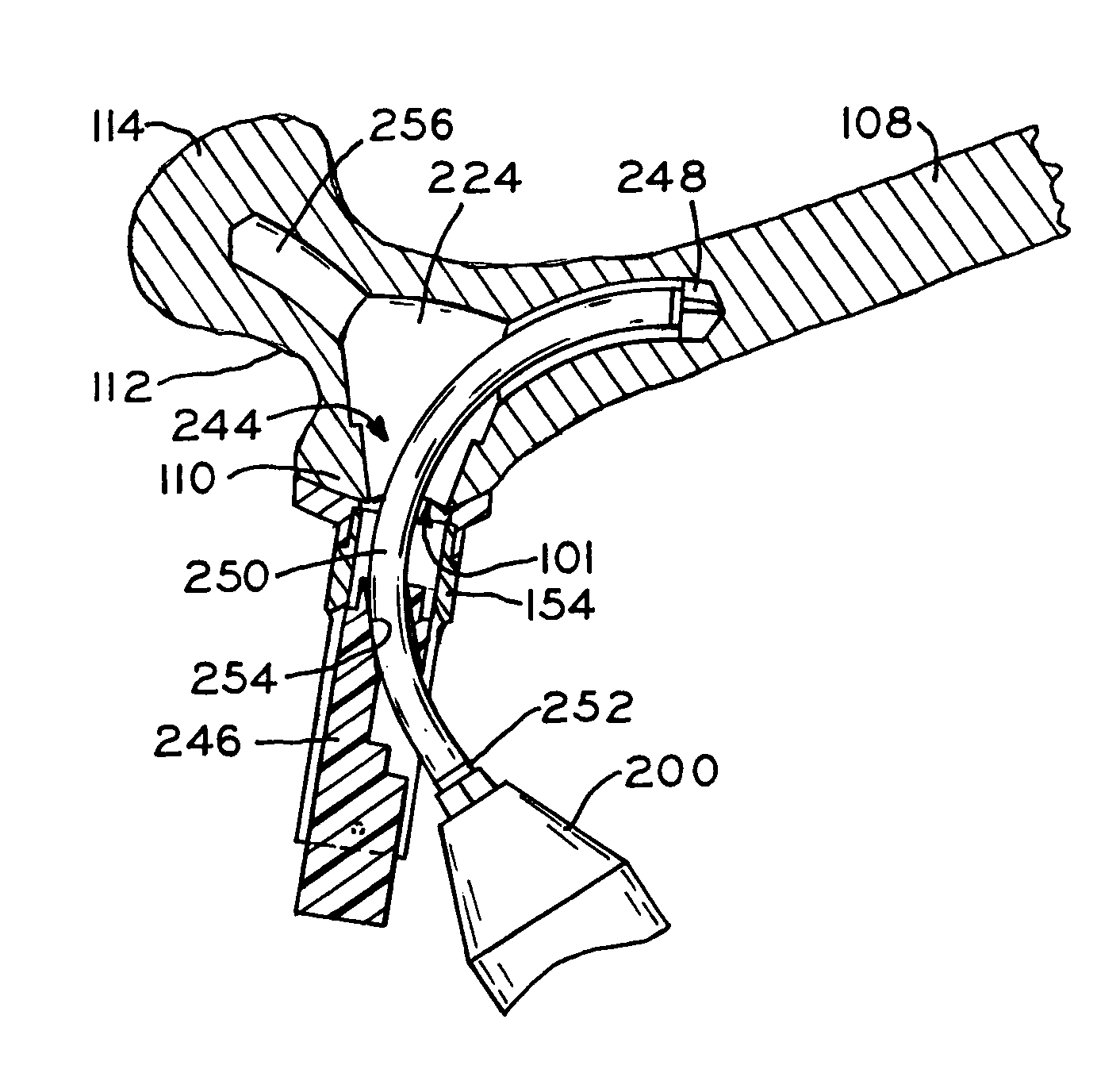
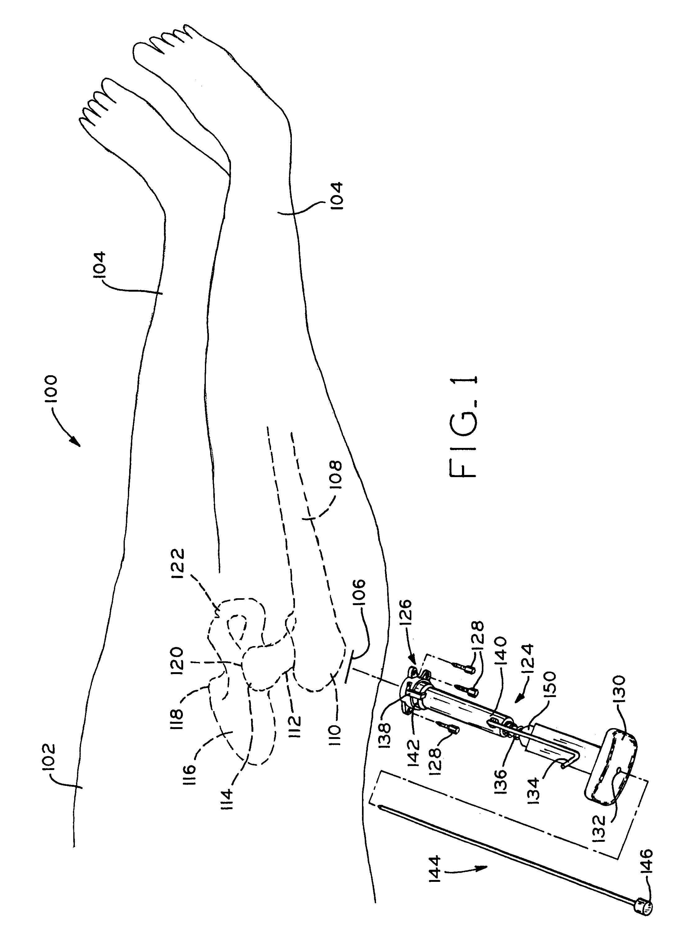
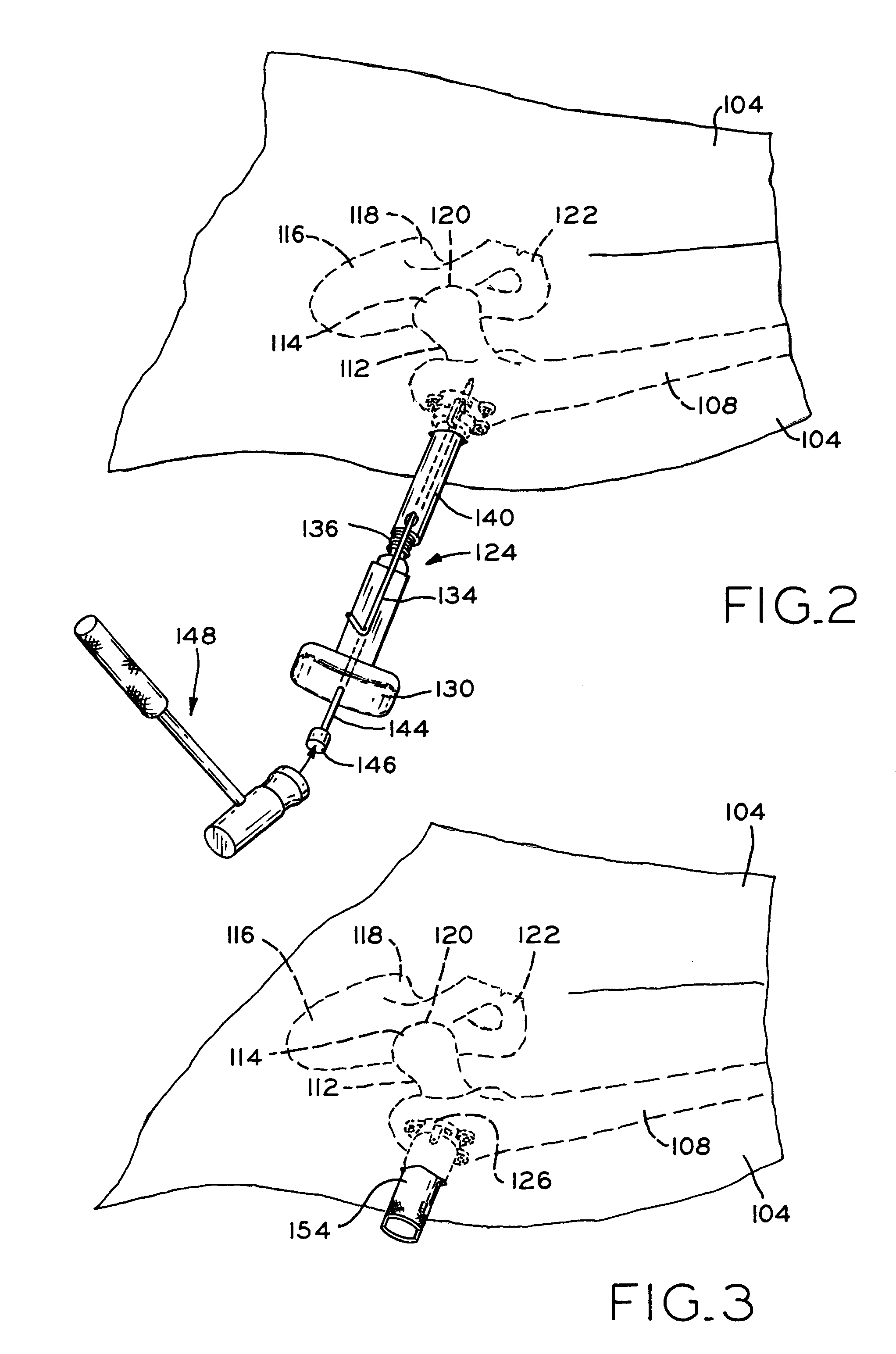
[0102]Implant 260 illustrated in FIG. 41 is utilized to reduce a femoral fracture utilizing a method of implantation which does not require incision of the quadriceps. As illustrated in FIG. 1, incision 106 is aligned with greater trochanter 110, with femur 108 being prepared to receive implant 260 through incision 106. As described above, greater trochanter 110 is not covered with muscle and therefore, incision 106 can be developed to expose greater trochanter 110 without requiring the incision of muscle. As illustrated in FIGS. 6-10, various novel reamers of the present invention are utilized to form femoral cavity 224 (FIG. 11). As illustrated in FIG. 12, implant 260 (further illustrated in FIGS. 41-43) is inserted into femoral cavity 224 via an access formed through greater trochanter 110. As illustrated in FIG. 13, lag screw 264 is advanced into femoral head 114 until lag screw threads 282 firmly engage femoral head 114 and lag screw 264 has achieved the position illustrated in...


PUM


Abstract

An improved method and apparatus for reducing a hip fracture utilizing a minimally invasive procedure which does not require incision of the quadriceps. A femoral implant in accordance with the present invention achieves intramedullary fixation as well as fixation into the femoral head to allow for the compression needed for a femoral fracture to heal. To position the femoral implant of the present invention, an incision is made along the greater trochanter. Because the greater trochanter is not circumferentially covered with muscles, the incision can be made and the wound developed through the skin and fascia to expose the greater trochanter, without incising muscle, including, e.g., the quadriceps. After exposing the greater trochanter, novel instruments of the present invention are utilized to prepare a cavity in the femur extending from the greater trochanter into the femoral head and further extending from the greater trochanter into the intramedullary canal of the femur. After preparation of the femoral cavity, a femoral implant in accordance with the present invention is inserted into the aforementioned cavity in the femur. The femoral implant is thereafter secured in the femur, with portions of the implant extending into and being secured within the femoral head and portions of the implant extending into and being secured within the femoral shaft.

Description

[0001]This application is a continuation-in-part of prior U.S. patent application Ser. No. 09 / 520,351, filed Mar. 7, 2000, now U.S. Pat. No. 6,447,514.BACKGROUND OF THE INVENTION[0002]1. Field of the Invention[0003]The present invention relates to a method and apparatus for treating hip fractures, and, more particularly, to a method and apparatus for reducing femoral fractures utilizing a minimally invasive procedure.[0004]2. Description of the Related Art[0005]Current procedures utilized to reduce hip fractures generally utilize a side plate / hip screw combination, i.e., a bone plate affixed to a lateral aspect of the femur and having a hip screw operably connected thereto, with the hip screw extending into the femoral head. To properly implant a side plate hip screw, a surgeon must dissect an amount of muscle to expose the femur and operably attach the bone plate and hip screw. Typically, the side plate hip screw requires an incision of about 10-12 cm through the quadriceps to expo...

Claims


Application Information

Patent Timeline
Patent Type & Authority Patents(United States)
IPC IPC(8): A61B17/56A61F2/30A61B17/00A61B17/16A61B17/17A61B17/74A61B17/88A61F2/28A61F2/32A61F2/46
CPCA61B17/1668A61B17/175A61B17/742A61B17/8805A61B17/8863A61B17/8875A61B17/164A61B17/1642A61B17/1735A61B17/7097A61B2017/00238A61B2017/00287A61B2017/00557A61B2017/1602A61F2002/2825A61F2002/30583A61F2210/0085A61B17/1615A61B17/1631
Inventor THELEN, SARAH L.LOZIER, ANTONY J.DIETZEL, STEVEN E.SISK, BILLY N.MILLER, RICKSTALCUP, GREGORY C.
Owner ZIMMER TECH INC
Why Eureka
Try Eureka