Marine propulsion assembly utilizing a dual opposed threaded drive shaft with taper

a technology of drive shaft and taper, which is applied in the direction of rotary propellers, couplings, valve construction, etc., can solve the problems of drive shaft vibration, torque loss, and drive shaft strength loss

Active Publication Date: 2019-03-26
AMG OPERATIONS LLC
View PDF12 Cites 0 Cited by
  • Summary
  • Abstract
  • Description
  • Claims
  • Application Information

AI Technical Summary

Problems solved by technology

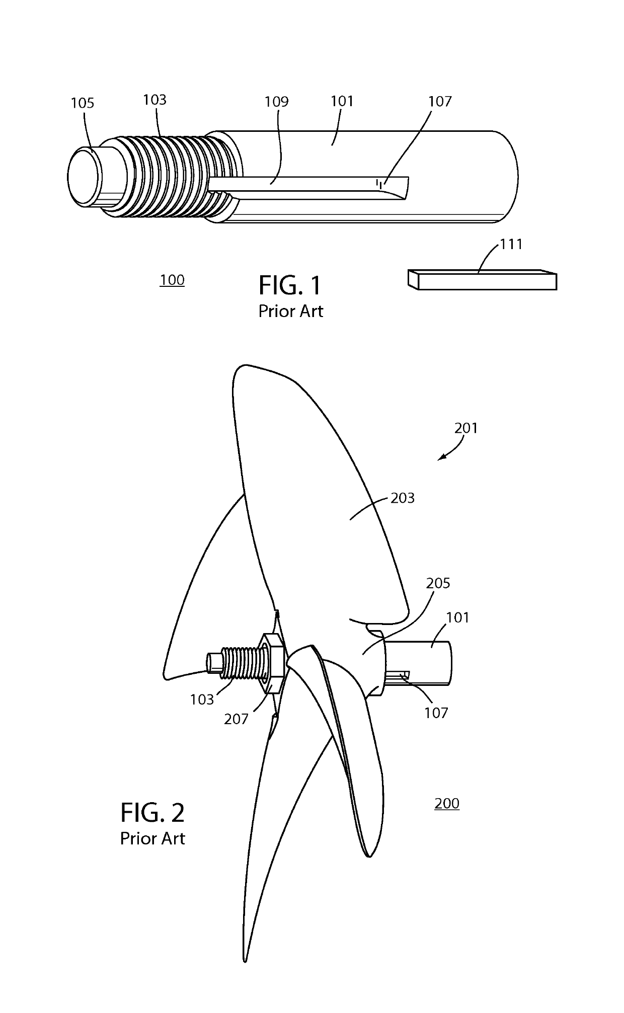
A problem often occurs during installation if the key does not seat properly within the keyed slot of the propeller and the keyed slot of the shaft.
Should the key slide forward and ride up the radius of the keyed slot in the shaft, it will create a pinching of the key and the keyed slot of the propeller forcing non fit / misalignment thus causing drive shaft vibration, loss of torque and drive shaft strength.

Method used


Image

  • Marine propulsion assembly utilizing a dual opposed threaded drive shaft with taper
  • Marine propulsion assembly utilizing a dual opposed threaded drive shaft with taper
  • Marine propulsion assembly utilizing a dual opposed threaded drive shaft with taper

Examples


Embodiment Construction

[0012]Before describing in detail embodiments that are in accordance with the present invention, it should be observed that the embodiments reside primarily in combinations of method steps and apparatus components related to a marine propulsion assembly. Accordingly, the apparatus components and method steps have been represented where appropriate by conventional symbols in the drawings, showing only those specific details that are pertinent to understanding the embodiments of the present invention so as not to obscure the disclosure with details that will be readily apparent to those of ordinary skill in the art having the benefit of the description herein.

[0013]In this document, relational terms such as first and second, top and bottom, and the like may be used solely to distinguish one entity or action from another entity or action without necessarily requiring or implying any actual such relationship or order between such entities or actions. The terms “comprises,”“comprising,” ...


PUM


Abstract

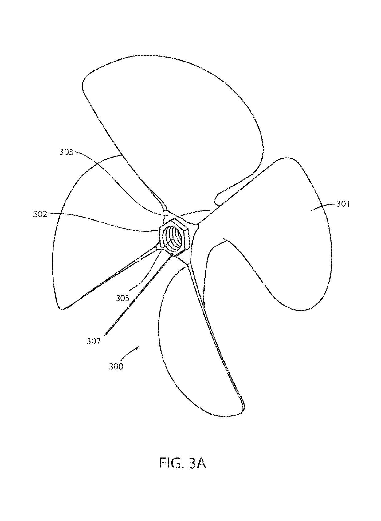
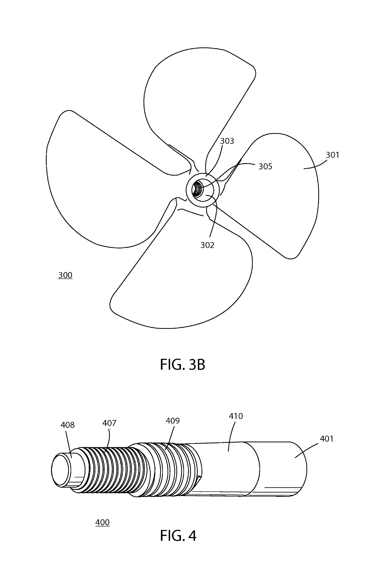
A marine propulsion assembly includes a propeller having a threaded hub whose threads are used for engaging with a drive shaft. The drive shaft includes both a first set of threads and second set of threads such that the first set of threads are used to engage with a keeper nut and a second set of threads are used to engage within the propeller hub. The first set of threads are configured to be opposite the direction of propeller rotation for preventing rotation of the keeper nut while the second set of threads are configured opposite the direction of rotation of the propeller to prevent the propeller from loosening on the drive shaft. The drive shaft further includes a tapered section for providing a stop to the propeller when engaging with the second set of threads.

Description

FIELD OF THE INVENTION[0001]The present invention relates generally to marine propulsion and more particular to a marine propeller and drive shaft assembly for use with Direct Drive / V Drive and Stern Drive marine engines utilizing drive shafts.BACKGROUND[0002]When used with marine propulsion systems, a drive shaft or propeller shaft (prop shaft) is a mechanical component used for transmitting torque and rotation to one or more marine propellers. The drive shaft connects components of the drive train, such as the marine motor, that cannot be connected directly to the propeller because of distance needed for allowing relative movement between these components. As a torque carrier, the drive shaft is subject to torsion and shear stress, equivalent to the difference between the input torque and the load. The drive shaft must be strong enough to bear the stress, whilst avoiding too much additional weight that would in turn increase its inertia.[0003]On a power-driven boat or ship, the dr...

Claims


Application Information

Patent Timeline
Patent Type & Authority Patents(United States)
IPC IPC(8): B63H23/34F16D1/08B63H1/20B63H1/14
CPCB63H23/34B63H1/14F16D1/0876B63H1/20B63B2749/00
Inventor DIEKEVERS, TODD
Owner AMG OPERATIONS LLC
Why Eureka
Try Eureka