Hook and methods of assembling and using the same

a technology of assembling and components, applied in the direction of hooks, load-engaging elements, fastening means, etc., can solve the problems of known hooks being difficult to secure to the components, hooks may undetectable decoupling from the components,

Active Publication Date: 2019-03-26
HONDA MOTOR CO LTD
View PDF24 Cites 0 Cited by
  • Summary
  • Abstract
  • Description
  • Claims
  • Application Information

AI Technical Summary

Problems solved by technology

In use, known hooks may be difficult to secure to the component.
Consequently, the hook may shift in use, causing the component to shift along a portion of the hook not designed to bear the full load of the component, or the hook may undesirably de-couple from the component.

Method used


Image

  • Hook and methods of assembling and using the same
  • Hook and methods of assembling and using the same
  • Hook and methods of assembling and using the same

Examples


Embodiment Construction

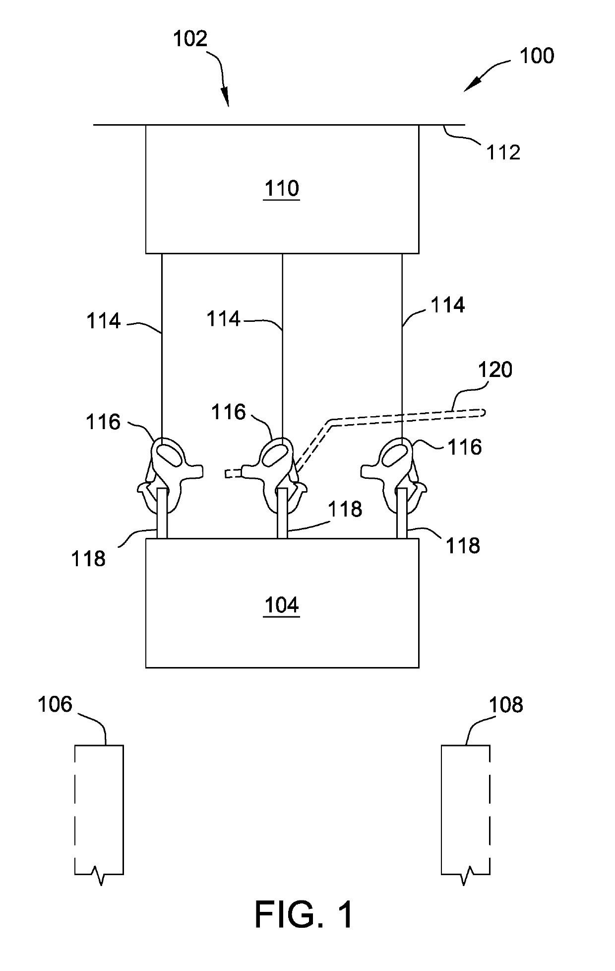
[0011]The present disclosure relates generally to transport systems for use with assembly lines, and, more specifically, to hooks for use in securely coupling components to transport systems to enable the components to be moved to different stations along an assembly line. As described in more detail below, at least some exemplary embodiments of the hook include a hook body, a latch pivotably coupled to the hook body, and a biasing element coupled to the latch. The biasing element maintains the latch in a first, open position when no load is applied to the hook. When a load is applied to the hook (e.g., when the component is being lifted and / or transported), the latch pivots with respect to the hook body to securely close an opening of the hook, preventing the component from de-coupling from the hook.

[0012]FIG. 1 is a schematic diagram of an exemplary automotive assembly line 100. In the exemplary embodiment, automotive assembly line 100 includes a transport system 102 that transpor...


PUM


Abstract

A hook for lifting a component includes a hook body and a latch. The hook body includes a coupling portion having an elongate aperture defined therein for receiving at least a portion of a chain, and an engaging portion extending from the coupling portion, the engaging portion defining a hook opening sized for receiving a first portion of the component therein. The latch is pivotably coupled to the coupling portion and pivotable between a first position and a second position relative to the hook body. The latch occludes the hook opening in the second position. The latch defines a chain aperture that is aligned with the elongate aperture such that the portion of the chain extends through each of the elongate aperture and the chain aperture and causes the latch to pivot between the first and second positions in response to a load being applied to the hook.

Description

BACKGROUND[0001]The present disclosure relates generally to transport systems for assembly lines, and, more specifically, to hooks for coupling components to transport systems to facilitate moving the components to different stations of an assembly line.[0002]At least some production or assembly lines employ conveyors to transport components between different stations of the production line. Some known conveyors are mounted to a horizontal rail, and roll along that rail to move components between stations on the production line. At least some known conveyors include a chain that is coupled to the component via one or more hooks. In use, known hooks may be difficult to secure to the component. Consequently, the hook may shift in use, causing the component to shift along a portion of the hook not designed to bear the full load of the component, or the hook may undesirably de-couple from the component.BRIEF SUMMARY[0003]In one aspect, a hook for lifting a component is provided. The hoo...

Claims


Application Information

Patent Timeline
Patent Type & Authority Patents(United States)
IPC IPC(8): B66C1/36F16B45/02B66C1/34B65G19/02
CPCF16B45/025B66C1/36B66C1/34B65G19/02F16B45/021
Inventor MACARTHUR, BENJAMIN B.SWITZER, DWAYNE
Owner HONDA MOTOR CO LTD
Why Eureka
Try Eureka