Fabric handling apparatus

a technology of material handling and material handling, which is applied in the field of construction and can solve the problems of lack of precise reproducibility, prone to errors in manual processes, and difficulty in ensuring the quality of materials, and achieves the effect of constant position relationship

Active Publication Date: 2019-04-23
SHORT BROTHERS
View PDF32 Cites 2 Cited by
  • Summary
  • Abstract
  • Description
  • Claims
  • Application Information

AI Technical Summary

Benefits of technology

[0027]It also is contemplated that the present invention provides a fabric handling apparatus where the fabric handling array further comprises a frame and the attractors are suspended from the frame such that the attractors are displaceable vertically with respect to the frame. In this embodiment, a height adjustment device operably connected to each attractor to displace the attractor vertically with respect to the frame. Moreover, in a further variant, a cable extending between each height adjustment device and the attractor. Spooling of the cable permits displacement of the attractor with respect to the frame.
[0028]It is contemplated that the fabric handling apparatus of the present invention may include a plurality of connectors connecting adjacent ones of the attractors to one another to maintain the attractors in a substantially constant positional relationship with respect to each other.
[0029]In one contemplated embodiment, the connectors each include a rigid shaft and two ball joints, one at each end of the rigid shaft. The ball joints allow angular displacement of the rigid shaft when the attractors move vertically with respect to one another.

Problems solved by technology

Production time is therefore an issue.
As should be apparent to those skilled in the art, manual processes are prone to error and may, in some instances, lack precise reproducibility.
It is known, for example, that manual handling of fabric materials may result in stretching or creasing of the fabric material.
In addition, if gripping tools are used, the gripping tools may damage the fabric during handling, especially at the locations where the gripper tools are used.
These deformations may adversely affect the ability to produce a composite component by increasing production times, especially if damaged fabric plies need to be removed and replaced prior to final formation of the composite component.
It is the first of these two techniques that presents particular challenges to the manufacturer of composite components.

Method used


Image

  • Fabric handling apparatus
  • Fabric handling apparatus
  • Fabric handling apparatus

Examples


Embodiment Construction

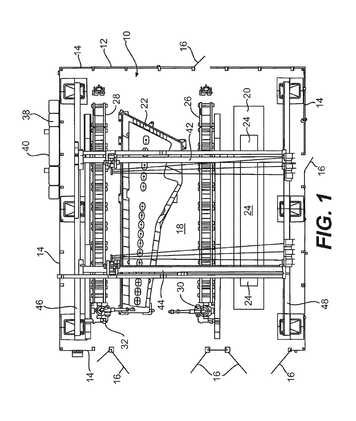
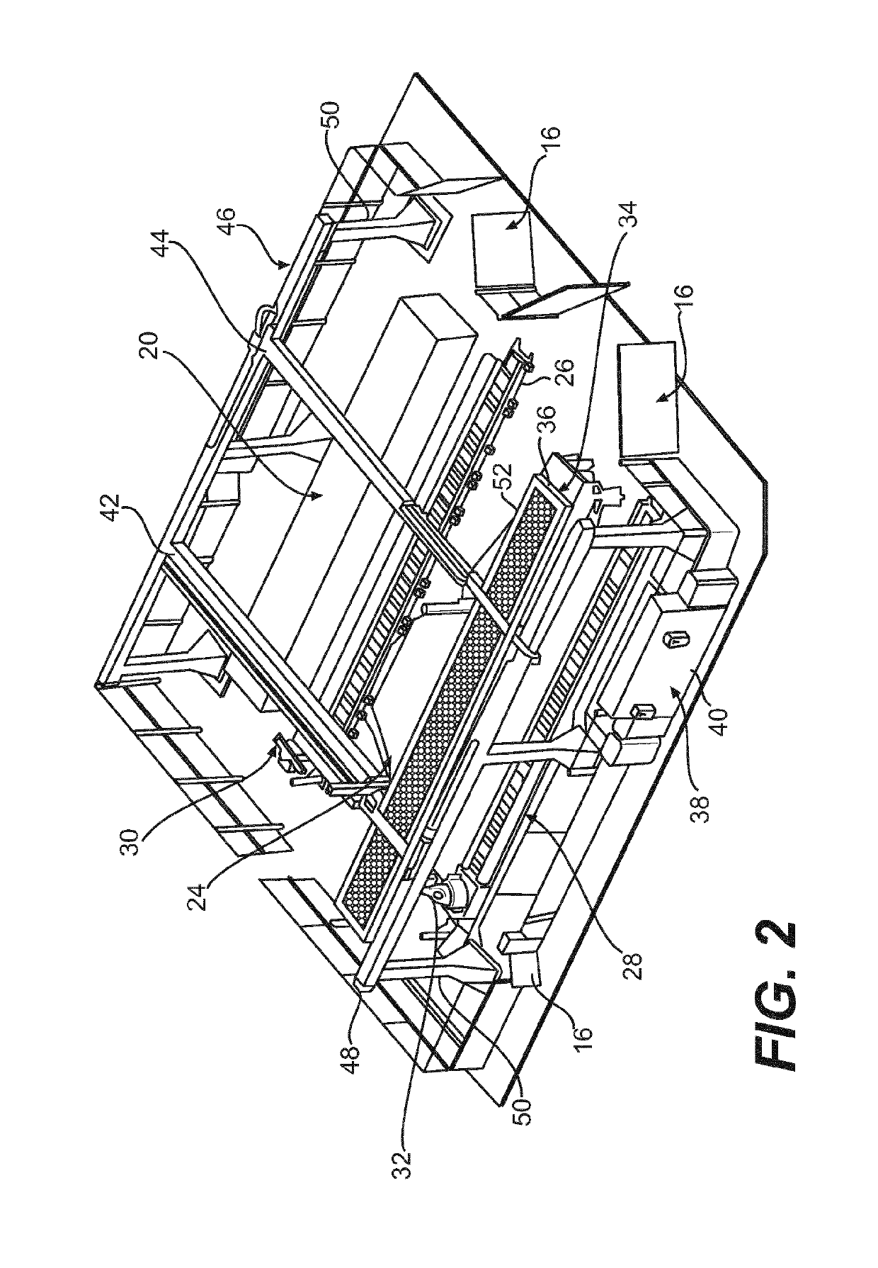
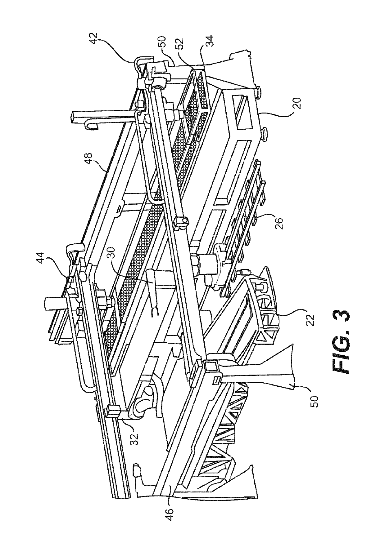
[0074]The present invention will now be described in connection with one or more embodiments. Discussion of any one particular embodiment is intended to be illustrative of the breadth and scope of the invention. In other words, while attention is focused on specific embodiments, those embodiments are not intended to be limiting of the scope of the present invention. To the contrary, after appreciating the discussion and drawings presented herein, those skilled in the art will readily appreciate one or more variations and equivalents of the embodiments described and illustrated. Those variations and equivalents are intended to be encompassed by the present invention as though they were described herein.

[0075]The modern manufacture of aircraft has recently departed from traditional reliance upon aluminum and aluminum alloys for the external components of the aircraft and moved to a greater reliance on composite materials. It is anticipated that future aircraft will rely even more heav...


PUM

PropertyMeasurementUnit
distanceaaaaaaaaaa
shapeaaaaaaaaaa
displacementaaaaaaaaaa

Abstract

A fabric handling apparatus includes a layup table, a mold disposed adjacent to the layup table, and a fabric handling array suspended above the layup table and the mold. The fabric handling array is adapted to transfer at least one fabric shape from the layup table to the mold. The fabric handling array includes a plurality of attractors in an attractor array. An orientation of the fabric handling array is alterable with respect to at least one of the layup table and the mold so that the at least one fabric shape is positionable on the mold in a predetermined orientation.

Description

CROSS-REFERENCE TO RELATED APPLICATIONS[0001]This is a National Stage Entry into the United States Patent and Trademark Office from International PCT Patent Application No. PCT / EP2012 / 076793 having an international filing date of Dec. 21, 2012, the entire contents of which are incorporated herein by reference.FIELD OF THE INVENTION[0002]The present invention concerns the construction and operation of an apparatus designed to lift, manipulate, and transfer fabric from a transfer station to a mold. More specifically, the apparatus of the present invention is designed to lift, manipulate, and transfer fabrics used to create composite materials, such as those employed for the construction of aircraft.DESCRIPTION OF THE RELATED ART[0003]The prior art includes examples of several devices that may be employed to handle fabric materials. This includes woven and non-woven fabric such as flexible carbon fabric.[0004]By way of background, as should be apparent to those skilled in the art, for ...

Claims


Application Information

Patent Timeline
Patent Type & Authority Patents(United States)
IPC IPC(8): B29C31/08B32B5/02B25J11/00B29C70/38B29C70/54B65H5/08B25J5/02B25J9/00B25J9/02B25J15/00B25J15/06B65H9/10B32B37/18B32B39/00B32B38/00D06M17/00D06M10/00B32B38/18
CPCB32B38/1808B25J5/02B25J9/0078B25J9/0084B25J9/026B25J11/00B25J15/0052B25J15/0616B29C31/085B29C70/38B29C70/545B32B5/02B32B37/18B32B38/0004B32B39/00B65H5/08B65H9/10D06M10/00D06M17/00B32B2309/70B32B2605/18B65H2402/30B65H2701/11312B65H2701/174Y10T83/0448Y10T83/2183Y10T156/17
Inventor JESS, ANDREWBOWMAN, LYNSEYFRAZER, PAUL
Owner SHORT BROTHERS
Why Eureka
Try Eureka