Rotor bearing member, photoconductor unit including the same, and image forming apparatus

A technology of rotor support and support member, which is applied to equipment, mechanical equipment, bearings, etc. using the electric recording process of charge pattern, can solve the problems of complex shape of support members, and achieve the advantages of reducing contact area, easy installation, and reducing sliding resistance. Effect

Active Publication Date: 2016-12-07
FUJIFILM BUSINESS INNOVATION CORP
View PDF5 Cites 0 Cited by
  • Summary
  • Abstract
  • Description
  • Claims
  • Application Information

AI Technical Summary

Problems solved by technology

Therefore, the shape of the supporting member is complicated

Method used


Image

  • Rotor bearing member, photoconductor unit including the same, and image forming apparatus
  • Rotor bearing member, photoconductor unit including the same, and image forming apparatus
  • Rotor bearing member, photoconductor unit including the same, and image forming apparatus

Examples


Embodiment Construction

[0039] Hereinafter, the present invention will be described in detail based on exemplary embodiments with reference to the accompanying drawings. However, the present invention is not limited to the exemplary embodiments described below.

[0040] Also, in the description with reference to the drawings, the drawings are schematic and not to scale. For easy understanding, illustration of those components other than those necessary for description will be appropriately omitted.

[0041] (first exemplary embodiment)

[0042] (1) Configuration of image forming apparatus

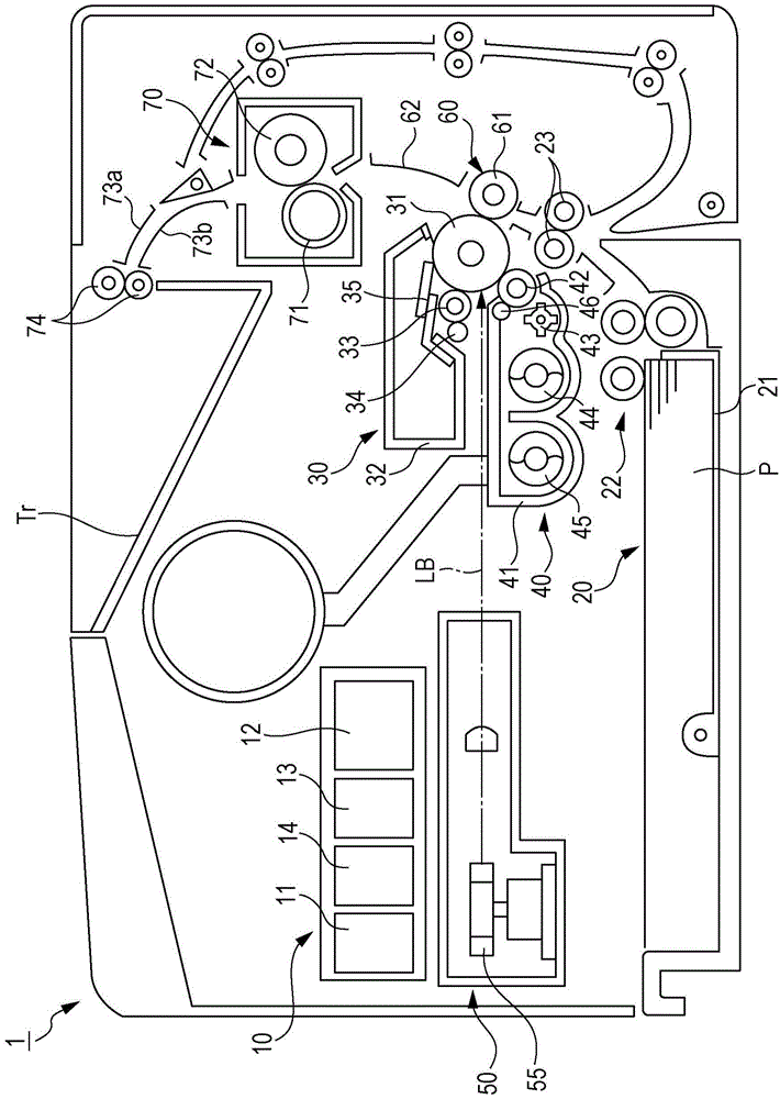
[0043] figure 1 is a schematic sectional view showing the internal configuration of the image forming apparatus 1 according to the present exemplary embodiment.

[0044] Hereinafter, the overall configuration and operation of the image forming apparatus 1 will be described with reference to the drawings.

[0045] The image forming apparatus 1 includes a control device 10 , a sheet feeder 20 , a photoreceptor ...


PUM


Abstract

The invention provides a rotor bearing member, a photoconductor unit including the same, and an image forming apparatus. The rotor bearing member is attached to a support body. The support body includes a guide section that supports a first member and a second member such that the first member and the second member are movable toward a rotor. The first member includes a rotary shaft and rotates about the rotary shaft thereof while being in contact with the rotor. The second member includes a rotary shaft extending along the rotary shaft of the first member and cleans a surface of the first member while rotating in contact with the first member. The rotor bearing member includes a first bearing member and a second bearing member that rotatably support the rotary shaft of the second member and the rotary shaft of the first member, respectively, while the first bearing member and the second bearing member abut each other.

Description

technical field [0001] The present invention relates to a rotor supporting member, a photoreceptor unit including the rotor supporting member, and an image forming apparatus. Background technique [0002] There is known a charging device that includes: a charging member that charges the surface of a charging target while rotating in contact with the charging target; a cleaning member that includes a The shaft rotates and removes unnecessary substances from the surface of the charging member while being rotated in contact with the charging member; and a supporting member including: a first receiving portion having an opening at one end thereof and a concave shape having a bottom at one end; and a second receiving portion having a concave shape open at one end thereof and having a bottom at the other end thereof. The first receiving portion receives the outer peripheral surface of the rotating shaft of the charging member at the bottom thereof. The second housing part accomm...

Claims


Application Information

Patent Timeline
IPC IPC(8): G03G15/02G03G21/16
CPCG03G15/0225G03G21/1647G03G21/1821G03G2221/1654F16C13/02F16C23/04G03G15/75
Inventor 福泽常夫星野弘久深井武夫福室浩司铃木健司市原宽一西村明仁
Owner FUJIFILM BUSINESS INNOVATION CORP
Why Eureka
Try Eureka