Rotor structure of Halbach motor and manufacturing method thereof

A technology of rotor structure and manufacturing method, which is applied in the rotor mechanism of Halbach motor and its manufacturing field, and can solve the problems that Halbach rotor cannot be mass-produced, the performance of small-scale production is poor, and the structural design is unreasonable, etc.

Pending Publication Date: 2018-11-02
NO 21 RESERCH INST OF CHINA ELECTRONICS TECH GRP
View PDF0 Cites 4 Cited by
  • Summary
  • Abstract
  • Description
  • Claims
  • Application Information

AI Technical Summary

Problems solved by technology

[0005] In the existing technology, the traditional Halbach rotor is composed of N-pole magnets, S-pole magnets and a rotating shaft. The N-pole magnets and S-pole magnets adopt a flat structure, and the N-pole magnets or S-pole magnets are attached to the rotating shaft. , There is a line contact between the patch (N pole magnet, S pole magnet) and the rotating shaft. Due to the difficulty of patching, the patching operation is usually done manually, and the manual patching operation will cause the error accumulation of the patch
Due to the complex structure of the Halbach rotor, it has problems such as poor manufacturability and inflexible design. It is precisely the existence of these problems that the Halbach rotor cannot be mass-produced, and even the performance of small-scale production is poor.
[0006] In summary, due to unreasonable structural design and cumbersome processing technology, the advantages of the Halbach rotor structure cannot be applied to actual production

Method used


Image

  • Rotor structure of Halbach motor and manufacturing method thereof
  • Rotor structure of Halbach motor and manufacturing method thereof
  • Rotor structure of Halbach motor and manufacturing method thereof

Examples


Embodiment Construction

[0033] The present invention will be described in detail below with reference to the accompanying drawings and examples. Each example is provided by way of explanation of the invention, not limitation of the invention. In fact, those skilled in the art will recognize that modifications and variations can be made in the present invention without departing from the scope or spirit of the invention. For example, features illustrated or described as part of one embodiment can be used on another embodiment to yield a still further embodiment. Therefore, it is intended that the present invention includes such modifications and variations as come within the scope of the appended claims and their equivalents.

[0034] In the description of the present invention, the terms "longitudinal", "transverse", "upper", "lower", "front", "rear", "left", "right", "vertical", "horizontal", " The orientations or positional relationships indicated by "top", "bottom", etc. are based on the orienta...


PUM


Abstract

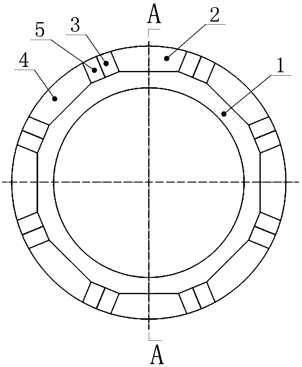
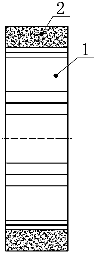
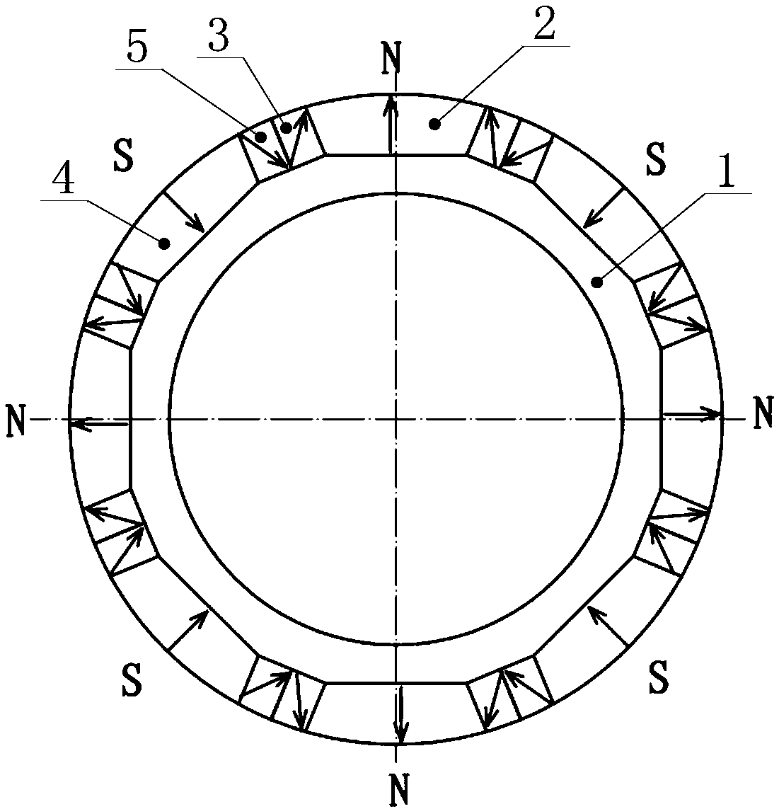
The invention provides a rotor structure of a Halbach motor. The rotor structure comprises N-pole magnetic steel, S-pole magnetic steel and a rotating shaft, wherein the N-pole magnetic steel comprises N-pole large magnetic steel and N-pole small magnetic steel; S-pole magnetic steel comprises S-pole large magnetic steel and S-pole small magnetic steel; and specific limitation is as follows: the magnetic force line inside the N-pole small magnetic steel is parallel to the diagonal line of the radial section of the N-pole small magnetic steel or has an acute angle included angle, and the magnetic force line inside the S-pole small magnetic steel is parallel to the diagonal line of the radial section of the S-pole small magnetic steel or has an acute angle included angle. The invention alsoprovides a manufacturing method of the rotor structure of the Halbach motor. The rotor structure has the advantages that a permanent magnet forming a magnetic group is simple in structural shape and low in processing difficulty; the installation operation is simple and convenient, the motor production efficiency is high, and the homogeneity of product is improved; the structure of the magnetic group is limited, the accumulative error during assembling can be eliminated, and the motor performance is improved; the cross area of the permanent magnet is larger, and a magnetic circuit inside the permanent magnet is longer, so that the demagnetizing resistance of the motor is promoted.

Description

technical field [0001] The invention relates to the technical field of motor equipment, and more specifically relates to a rotor mechanism of a Halbach motor and a manufacturing method thereof. Background technique [0002] The Halbach motor is a motor using the Halbach array magnet structure. The Halbach array magnet structure is an almost ideal magnet structure in engineering. The design goal of this structure is to generate the strongest magnetic field with the least amount of magnets. [0003] The Halbach array magnet structure uses a special arrangement of magnet units to enhance the field strength of the magnet unit in one direction. [0004] The Halbach rotor structure is applied to permanent magnet motors, which can build a special motor magnetic field circuit, which can remove the rotor magnetic yoke structure of the motor, increase the air gap magnetic density, optimize the air gap waveform, effectively improve the performance of the motor, reduce the Small motor ...

Claims


Application Information

Patent Timeline
Patent Type & Authority Applications(China)
IPC IPC(8): H02K1/27H02K15/03
CPCH02K1/276H02K15/03
Inventor 钱荣超
Owner NO 21 RESERCH INST OF CHINA ELECTRONICS TECH GRP
Why Eureka
Try Eureka