Photonic crystal fiber with tunable broadband polarization filtering

A technology of photonic crystal fiber and polarization filtering, which is applied in the direction of cladding fiber, optical waveguide and light guide, etc., can solve the problems that the polarization filtering effect cannot be well realized, achieve simple and selective filling, improve birefringence, and reduce structural errors Effect

Active Publication Date: 2019-08-27
青岛君戎汇通光电科技有限公司
View PDF8 Cites 0 Cited by
  • Summary
  • Abstract
  • Description
  • Claims
  • Application Information

AI Technical Summary

Problems solved by technology

Recently, X. Zhang et al. used the reduction reaction precipitation method to selectively coat the inner walls of the two air holes of the photonic crystal fiber with a layer of silver film. At the same time, they found that the fiber has a polarization absorption effect, but it cannot achieve two positive Polarization filtering effect with complete separation of cross polarization directions

Method used


Image

  • Photonic crystal fiber with tunable broadband polarization filtering
  • Photonic crystal fiber with tunable broadband polarization filtering
  • Photonic crystal fiber with tunable broadband polarization filtering

Examples


Embodiment 1

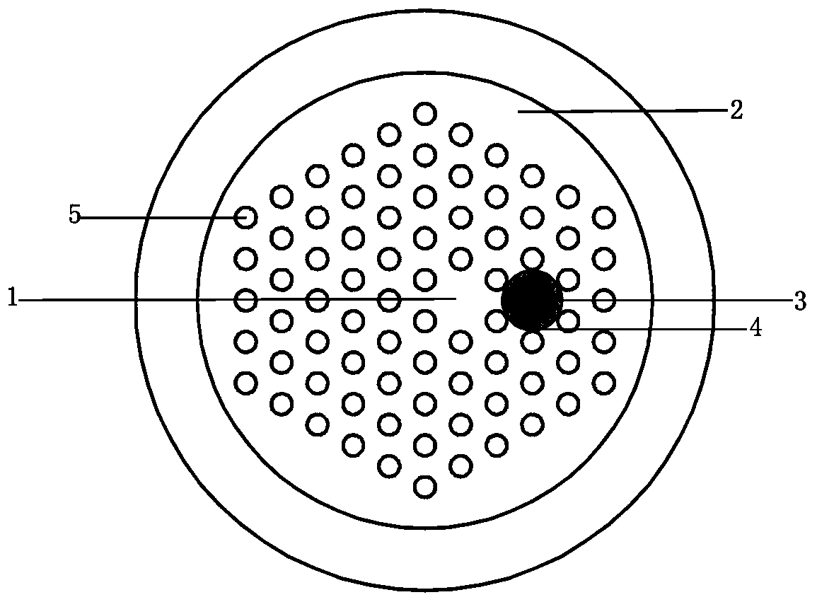
[0024] figure 1 It is an embodiment of the photonic crystal fiber with a novel structure with tunable broadband polarization filtering function in the present invention. The background material 2 of the optical fiber is a quartz material, and the air holes 5 forming the cladding area are evenly distributed on each node of the equilateral triangle array. The core area 1, the diameter of the large air hole 3 on the right side of the core area 1 is 2.4 microns, and a layer of gold film 4 is coated on the inner wall. The thickness of the gold film 4 is 23 nanometers, and the refractive index is filled in the large air hole 3 1.38 liquid, and the remaining air holes 5 have the same size, with a diameter of 1 micron.

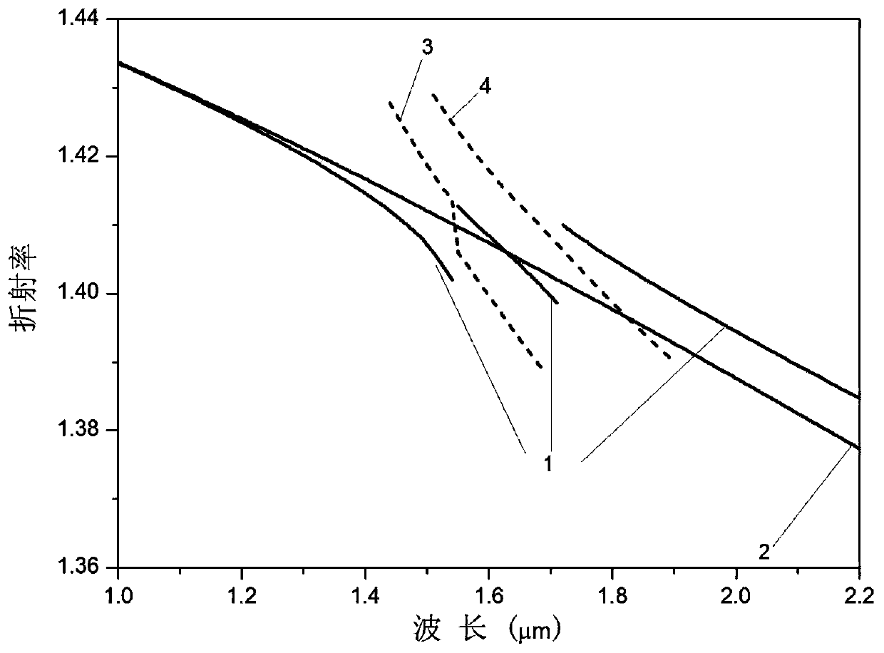
[0025] figure 2 It is the dispersion relationship diagram of the optical fiber of the first embodiment of the present invention. Curves 1 and 2 are the relationship between the effective refractive index of the fundamental mode in the x-polarization direction and ...

Embodiment 2

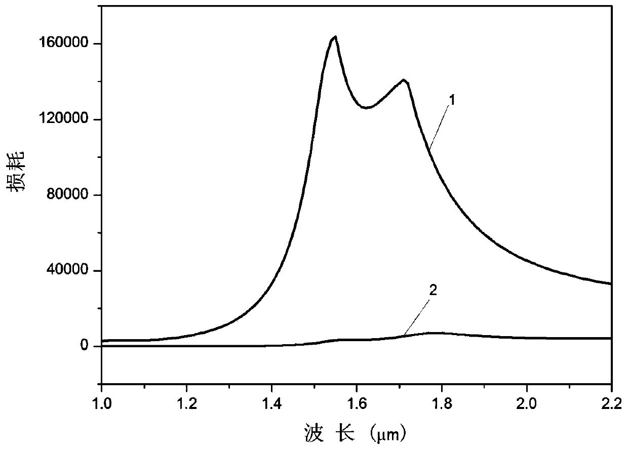
[0029] Figure 5 It is the transmission loss diagram of Embodiment 2 of the optical fiber of the present invention. Embodiment 2 of the present invention has the same structure as Embodiment 1, except that the refractive index of the liquid filled in the large air holes in Embodiment 2 is 1.3. Curves 1 and 2 are the transmission losses of optical fibers in two orthogonal polarization directions x and y respectively. It can be clearly seen from the figure that the fundamental mode in the x-polarization direction of the fiber and the SPPs on the surface of the gold film produce resonance responses at 1.31 microns and 1.45 microns, respectively. Therefore, by changing the refractive index of the filled liquid, the polarization filtering of the two communication bands of 1.55 microns and 1.31 microns is conveniently realized, and the filtering functions at other wavelengths can also be obtained by the same method. This embodiment well demonstrates the tunable filtering character...


PUM


Abstract

The invention discloses a novel-structure photonic crystal fiber with tunable broadband polarization filtering. The photonic crystal fiber is composed of a background material, a fiber core, a defectcore and a cladding region; on the background material, a plurality of round air holes with the same aperture are arranged in the regular triangular structure periodically to form the cladding region;an air hole in the right side of the structure center is missed to form a fiber core; a large air hole is formed in the right side of the fiber core, a gold film is plated on the inner wall of the large air hole, and liquid is filled in the large air hole covered with the gold film to form a defect core area. The photonic crystal fiber provided by the invention can achieve a good tunable broadband polarization filtering function, and can be applied to a polarization filter element based on optical fibers.

Description

technical field [0001] The invention relates to a photonic crystal fiber with novel structure and tunable broadband polarization filtering function. The photonic crystal fiber can realize good broadband polarization filtering function in different wave bands, and can be applied to polarization filter devices based on optical fiber. Background technique [0002] With the continuous development of optical fiber communication, optical fiber sensing, fiber laser and optical information processing technology, the use of polarization filter devices is becoming more and more extensive, and the demand for tunable broadband polarization filter devices is particularly prominent. At the same time, the development trend of miniaturization and integration of optical devices is becoming more and more obvious. Photonic crystal fibers are favored by people in the application of optical fibers and their devices because of their flexible and controllable microstructure and optical characteris...

Claims


Application Information

Patent Timeline
Patent Type & Authority Patents(China)
IPC IPC(8): G02B6/02
Inventor 陈海良刘英超李曙光
Owner 青岛君戎汇通光电科技有限公司
Why Eureka
Try Eureka