Birefringent micro-structured optical fiber for sensor application

a micro-structured, optical fiber technology, applied in the direction of optical elements, instruments, manufacturing tools, etc., can solve the problems of inability to tailor the temperature sensitivity of an fbg in such a mof, and the mechanical-to-thermal sensitivity ratio is currently moderate, so as to reduce confinement losses

Active Publication Date: 2012-09-06
POLITECHNA WROCLAWSKA WROCLAW UNIV OF TECH +2
View PDF1 Cites 11 Cited by
  • Summary
  • Abstract
  • Description
  • Claims
  • Application Information

AI Technical Summary

Benefits of technology

[0035]Optical fibers according to embodiments of the present invention have a central microstructure that determines the direction of the slow and fast axis of the optical fiber with respect to the side holey structures and as a result determines the sensitivity of the Bragg peak wavelengths that corresponds to the slow and fast axes for an FBG in that fiber and also determines a positive or negative sign of the differential Bragg peak sensitivity.
[0036]Referring to the second aspect of the invention, the macrostructure preferably comprises at least two side-holes arranged opposite to each other and is adapted for determining the phase modal birefringence of the fiber structure. Preferably, the shape of the two

Problems solved by technology

However, in the fiber structures presently known the ratio of mechanical to thermal sensitivity i

Method used


Image

  • Birefringent micro-structured optical fiber for sensor application
  • Birefringent micro-structured optical fiber for sensor application
  • Birefringent micro-structured optical fiber for sensor application

Examples


Embodiment Construction

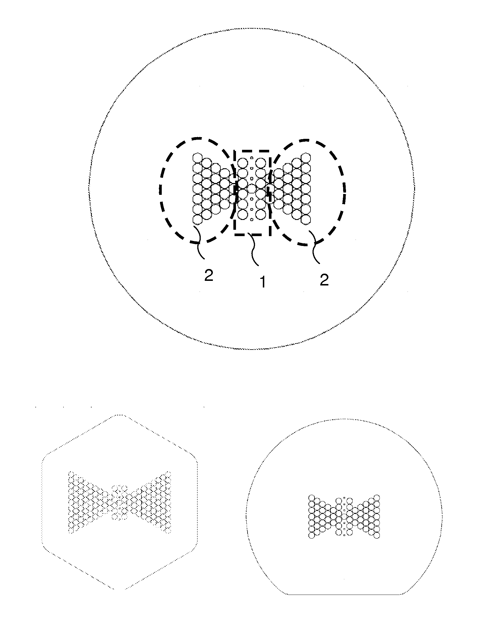
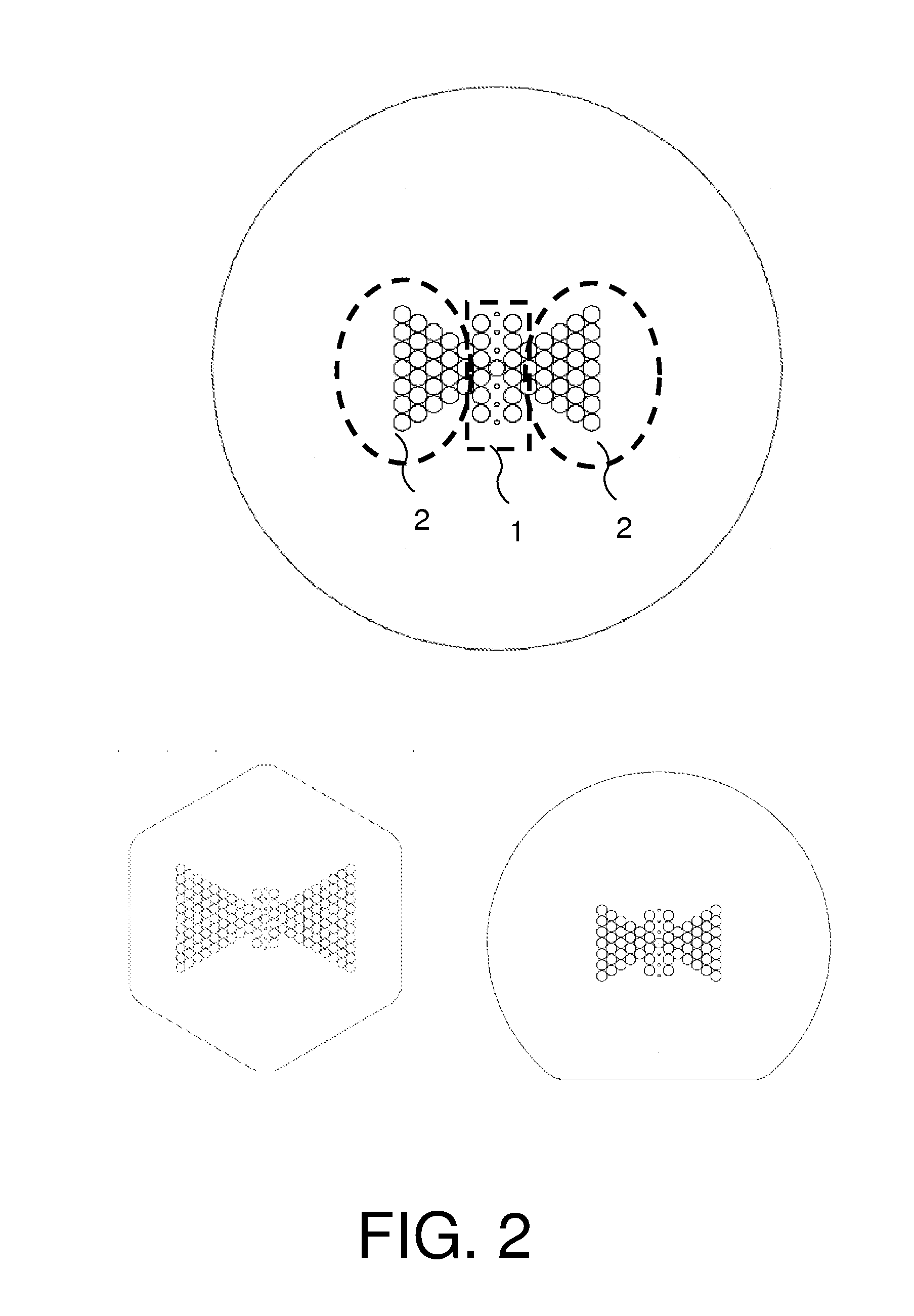
[0052]The present invention will be described with respect to particular embodiments and with reference to certain drawings but the invention is not limited thereto but only by the claims. The drawings described are only schematic and are non-limiting. In the drawings, the size of some of the elements may be exaggerated and not drawn on scale for illustrative purposes. The dimensions and the relative dimensions do not correspond to actual reductions to practice of the invention.

[0053]Furthermore, the terms first, second, third and the like in the description and in the claims, are used for distinguishing between similar elements and not necessarily for describing a sequential or chronological order. It is to be understood that the terms so used are interchangeable under appropriate circumstances and that the embodiments of the invention described herein are capable of operation in other sequences than described or illustrated herein.

[0054]Moreover, the terms top, bottom, over, under...


PUM

PropertyMeasurementUnit
Fractionaaaaaaaaaa
Pressureaaaaaaaaaa
Diameteraaaaaaaaaa

Abstract

Fiber structure including a core and a cladding, a central microstructure having a first plurality of longitudinal holes and which is adapted for guiding optical radiation and for birefringence in the core. Also included is a side microstructure having a second plurality of longitudinal holes is provided, wherein the side microstructure partly surrounds the central microstructure and provides a predetermined mechanical anisotropy, a pressure responsive unit for converting an isotropic pressure force to birefringence changes on the core, a lateral force responsive unit for converting a directional pressure force to birefringence changes on the core, a temperature responsive unit for converting temperature to birefringence changes on the core, and a birefringence responsive unit for converting birefringence in the core to wavelength information.

Description

FIELD OF THE INVENTION[0001]The invention relates to the field of fiber structures, preferably adapted for use with fiber Bragg gratings in sensors as well as to optical systems using such fibers and method of operating and making such devices.BACKGROUND OF THE INVENTION[0002]A photonic crystal fiber, PCF for short, is a class of optical fiber based on the properties of photonic crystals. Due to the ability to confine light in hollow cores or with confinement characteristics not possible in conventional optical fiber, PCF is finding applications in fiber optic communications, fiber lasers, non-linear devices, high power transmission, highly sensitive gas sensors and in other areas. In the following, PCFs using air holes in their cross sections are also called “holey fiber”.[0003]However, in the fiber structures presently known the ratio of mechanical to thermal sensitivity is currently moderate.[0004]Most existing results on the sensitivity of birefringent microstructured optical fi...

Claims


Application Information

Patent Timeline
IPC IPC(8): G02B6/34C03B37/023
CPCG02B6/02109G02B6/02338G02B6/02357G01D5/353G02B6/105G01D5/35316G01D5/3538G02B6/02371
Inventor GEERNAERT, THOMASBERGHMANS, FRANCISNASILOWSKI, TOMASZTHIENPONT, HUGOMAKARA, MARIUSZMERGO, PAWELPOTURAJ, KRZYSZTOF GRZEGORZURBANCZYK, WACLAWMARTYNKIEN, TADEUSZOLSZEWSKI, JACEK MAREKWOJCIK, JAN JOZEF
Owner POLITECHNA WROCLAWSKA WROCLAW UNIV OF TECH
Why Eureka
Try Eureka