Finite element analysis-based large-scale equipment lifting lug design and optimization method

A large-scale equipment and optimization method technology, applied in the direction of design optimization/simulation, calculation, instruments, etc., can solve problems such as the inability to analyze the local stress change of the stress tube joint of the lifting lug, the inability to consider the influence of the attachment, and the inability to calculate the size of the lifting lug. Achieve the effects of improving design accuracy and efficiency, optimizing the size of lifting lugs, saving materials and processing costs

Active Publication Date: 2022-07-08
CHINA CONSTR IND & ENERGY ENG GRP CO LTD +1
View PDF8 Cites 0 Cited by
  • Summary
  • Abstract
  • Description
  • Claims
  • Application Information

AI Technical Summary

Problems solved by technology

[0003] Compared with standard lifting lugs, non-standard lifting lugs often need to weld additional auxiliary reinforcement plates. The influence of this attachment is often not considered in the calculation of traditional lifting lug strength design, resulting in large calculation deviations
For lifting lugs with a nominal lifting weight greater than 300t or corresponding to a thinner tube section, not only the strength of the tube itself needs to be checked but also the local stress of the tube section needs to be calculated. However, the traditional lifting lug design method is too simplified when calculating the local stress, and there are some lifting lugs. The problem that the size cannot be calculated
At the same time, during the hoisting process, the load on the lifting lug and the load angle are constantly changing. The traditional lifting lug design method only considers the two working conditions of the equipment lifting angle of 0° and 90°, and cannot analyze the stress of the lifting lug and the cylinder during the hoisting process. Nodal local stress change

Method used


Image

  • Finite element analysis-based large-scale equipment lifting lug design and optimization method
  • Finite element analysis-based large-scale equipment lifting lug design and optimization method
  • Finite element analysis-based large-scale equipment lifting lug design and optimization method

Examples


Embodiment Construction

[0044] The present invention will be further described below with reference to the accompanying drawings and specific embodiments, but the protection scope of the present invention is not limited thereto.

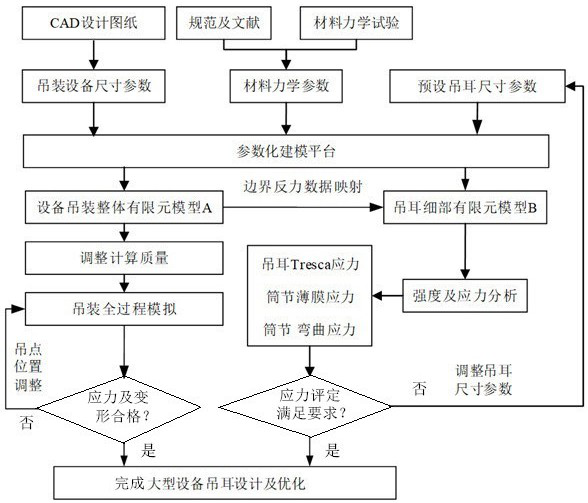
[0045] The method for optimizing the design of the lifting lug of large-scale equipment based on finite element analysis according to the present invention is as follows: figure 1 shown, including the following steps:

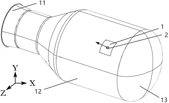
[0046] Step 1: Obtain size parameter information according to the CAD design drawing of the equipment. The size parameter information in this embodiment includes the size of the head 11 of the equipment, the nominal diameter, the thickness, the nominal diameter and thickness of the cylinder section 12, and the size of the skirt 13; according to the specification document And the material mechanical parameters of the equipment obtained from the material mechanical test, the material mechanical parameters include elastic modulus, Poisson's ratio, yield strengt...


PUM


Abstract

The invention provides a large-scale equipment lifting lug design and optimization method based on finite element analysis, and the method comprises the steps: building a lifting overall analysis finite element model and a lifting lug strength and local stress refining model, and adjusting the quality of the finite element model through introducing a gravitational acceleration amplification coefficient. And adjusting and determining a proper lifting point position according to the overall stress and deformation of the equipment. According to the invention, based on boundary data mapping between two models, the number of computational grids is reduced, and the computational efficiency and precision are improved; the lifting lug strength is calculated based on the strength theory, the shell ring film stress and the surface bending stress in the refined model are calculated based on the path stress linearization theory, stress evaluation is carried out, and then the lifting lug size is optimized. According to the method, the equipment lifting point position is designed and optimized through the finite element method, the size and shape differences of the lifting lugs are fully considered, the self strength of the lifting lugs and the local stress of the shell ring in the lifting process are accurately calculated, and the design precision and efficiency of the lifting lugs of the large equipment are improved.

Description

technical field [0001] The invention belongs to the technical field of large equipment lifting ear structure design, and in particular relates to a large equipment lifting ear design and optimization method based on finite element analysis. Background technique [0002] With the vigorous development of the country's energy and chemical industry, chemical equipment is gradually developing in the direction of heavy and large-scale. And the form is complex and changeable, there are problems such as large error, too conservative design and poor economy when using traditional specification methods to design and check. Therefore, in order to ensure the safety and stability of the equipment hoisting process, the reasonable and reliable position of the hoisting point, and the economical and reasonable size of the hoisting lug, it is necessary to carry out non-standard hoisting lug design and optimization research for large equipment. [0003] Compared with standard lifting lugs, no...

Claims


Application Information

Patent Timeline
Patent Type & Authority Applications(China)
IPC IPC(8): G06F30/23G06F30/17G06T17/20G06F119/14
CPCG06F30/23G06F30/17G06T17/20G06F2119/14
Inventor 张朝明徐梓豪徐艳红王会乾卓旬李乐吉怀军陈晓蓉任洁
Owner CHINA CONSTR IND & ENERGY ENG GRP CO LTD
Why Eureka
Try Eureka