Creative camera

a camera and creative technology, applied in the field of computer user interfaces, can solve the problems of cumbersome and inefficient techniques for displaying visual effects using electronic devices, complex and time-consuming user interfaces, and existing techniques that require more time than necessary, so as to improve efficiency, improve efficiency, and improve the effect of user experien

Active Publication Date: 2019-04-23
APPLE INC
View PDF188 Cites 90 Cited by
  • Summary
  • Abstract
  • Description
  • Claims
  • Application Information

AI Technical Summary

Benefits of technology

[0032]Thus, devices are provided with faster, more efficient methods and interfaces for displaying visual effects, thereby increasing the effectiveness,

Problems solved by technology

Some techniques for displaying visual effects using electronic devices, however, are generally cumbersome and inefficient.
For example, some existing techniques use a complex an

Method used


Image

  • Creative camera
  • Creative camera
  • Creative camera

Examples


Embodiment Construction

[0052]The following description sets forth exemplary methods, parameters, and the like. It should be recognized, however, that such description is not intended as a limitation on the scope of the present disclosure but is instead provided as a description of exemplary embodiments.

[0053]There is a need for electronic devices that provide efficient methods and interfaces for displaying visual effects. For example, while programs already exist for displaying visual effects, these programs are inefficient and difficult to use compared to the techniques below, which allow a user to displaying visual effects in various applications. Such techniques can reduce the cognitive burden on a user who displays visual effects in an application, thereby enhancing productivity. Further, such techniques can reduce processor and battery power otherwise wasted on redundant user inputs.

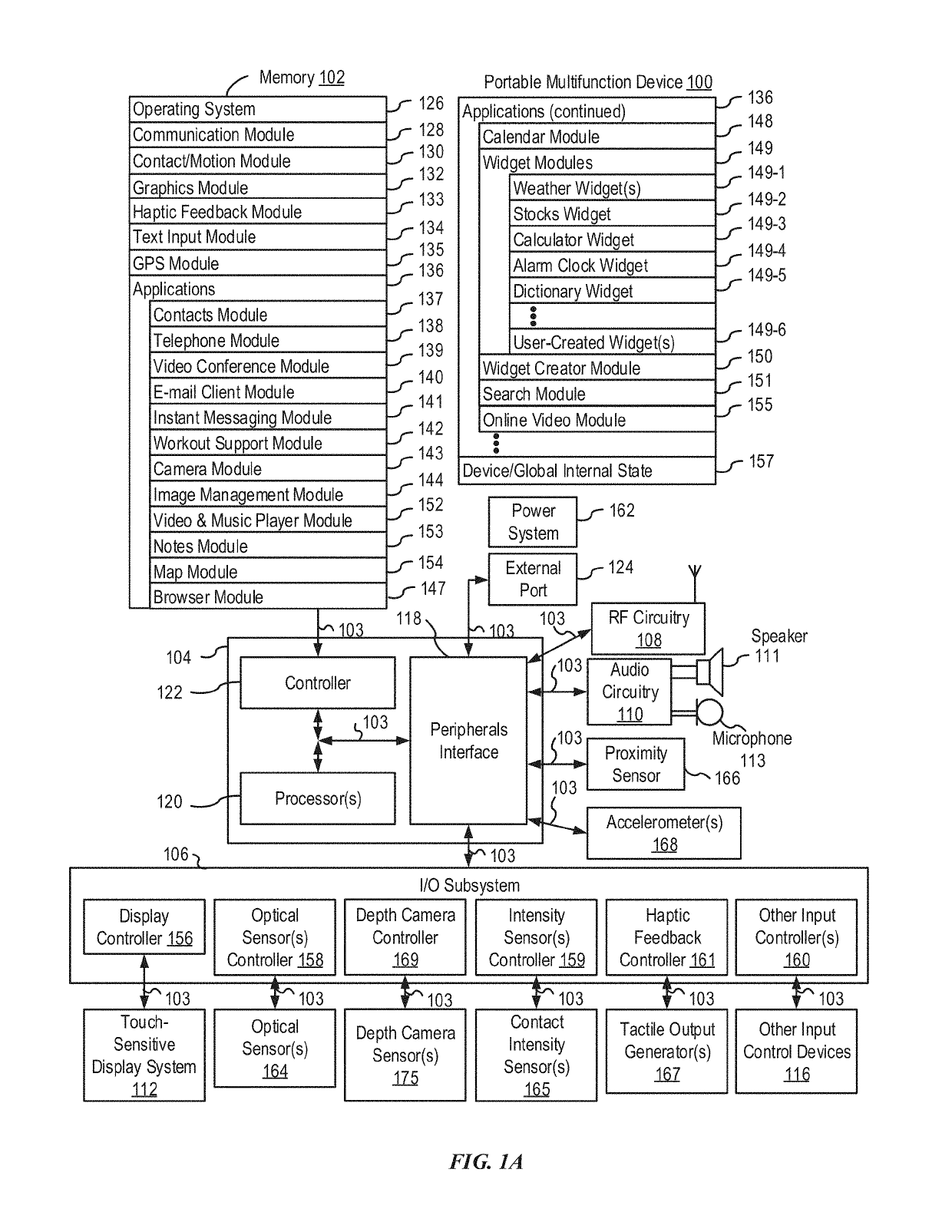
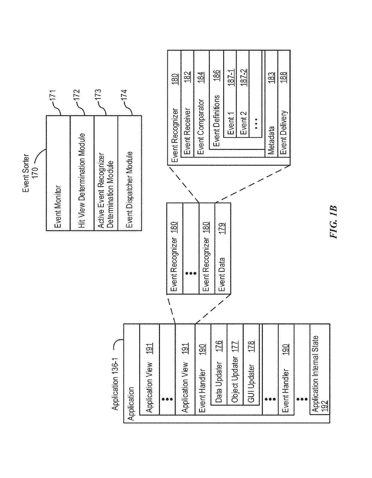
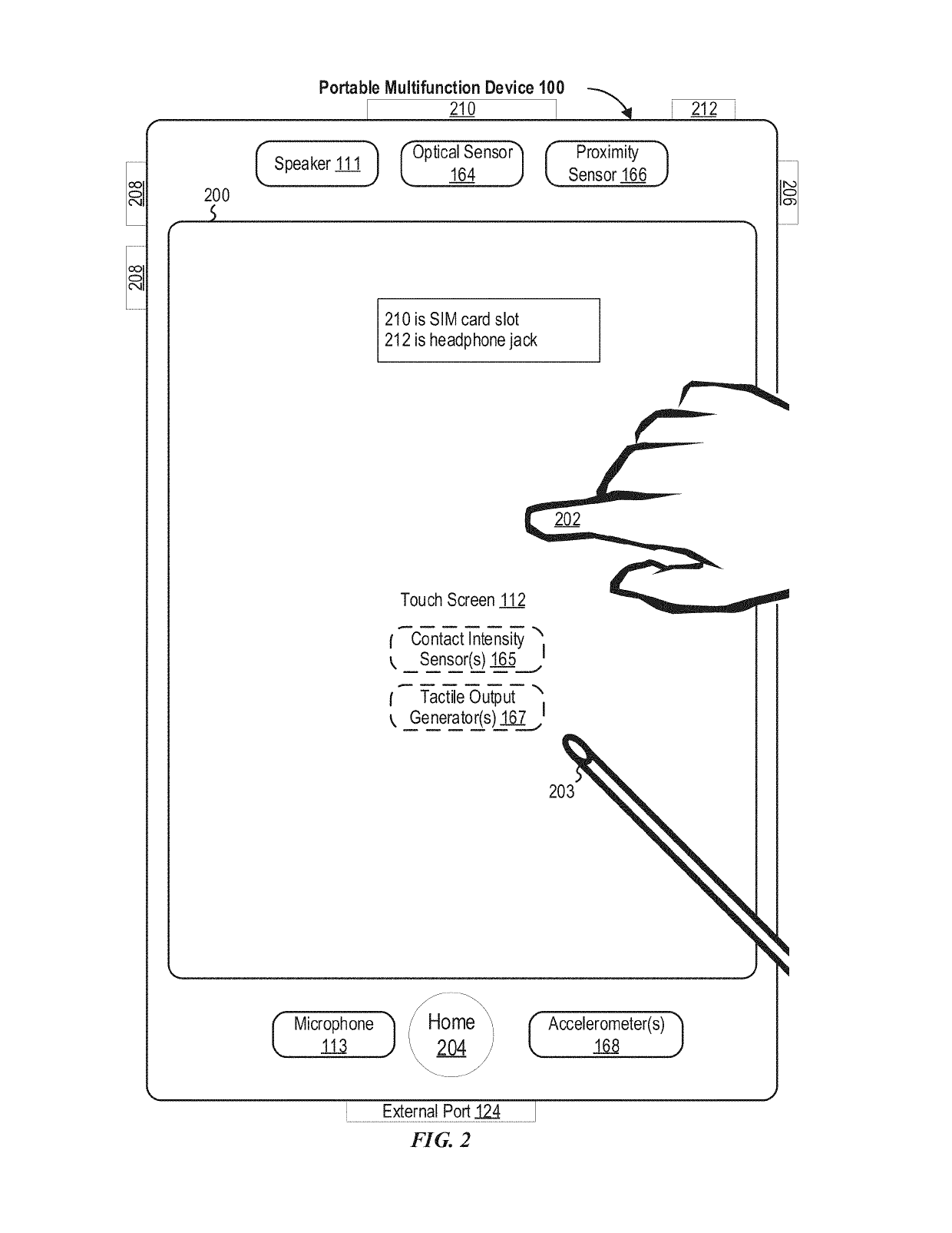
[0054]Below, FIGS. 1A-1B, 2, 3, 4A-4B, and 5A-5B provide a description of exemplary devices for performing the techniqu...


PUM


Abstract

The present disclosure generally relates to displaying visual effects in image data. In some examples, visual effects include an avatar displayed on a user's face. In some examples, visual effects include stickers applied to image data. In some examples, visual effects include screen effects. In some examples, visual effects are modified based on depth data in the image data.

Description

CROSS-REFERENCE TO RELATED APPLICATIONS[0001]This application claims the benefit of: U.S. Provisional Application No. 62 / 668,227, entitled “Creative Camera,” filed May 7, 2018, and U.S. Provisional Application No. 62 / 679,934, entitled “Creative Camera,” filed Jun. 3, 2018, the contents of which are hereby incorporated by reference in their entirety.FIELD[0002]The present disclosure relates generally to computer user interfaces, and more specifically to techniques for displaying visual effects.BACKGROUND[0003]Visual effects are used to enhance a user's experience when capturing and viewing media using electronic devices. Visual effects can alter the appearance of image data or can represent an idealized or completely fictional representation of an environment captured in an image.BRIEF SUMMARY[0004]Some techniques for displaying visual effects using electronic devices, however, are generally cumbersome and inefficient. For example, some existing techniques use a complex and time-cons...

Claims


Application Information

Patent Timeline
IPC IPC(8): H04N7/14H04N1/00H04N5/262H04N5/232G06F3/0484G06F3/0488
CPCH04N5/2621H04N7/141H04N5/23216H04N5/2628H04N5/23219G06F3/04842G06F3/04845G06F3/04883H04N7/147H04N2007/145G06F3/017G06F3/0304A61B5/744A61B5/1128H04N23/667H04N23/63G06T7/50G06T13/40G06T2207/30196H04N2005/2726H04L51/10H04M1/72439H04M1/72436H04N23/632H04N23/62H04N23/611G06T7/70H04N5/272
Inventor VAN OS, MARCELABOUKASM, JESSICABLACK, DAVID R.CHINN, ROBERTDUDEY, GREGORY L.ERNST, KATHERINE K.PAUL, GRANTWALSH, BRIAN E.CHANG, JAE WOOGUZMAN, AURELIOSCAPEL, NICOLAS
Owner APPLE INC
Why Eureka
Try Eureka