Printing apparatus and method of controlling printhead

a printing apparatus and printhead technology, applied in printing, other printing apparatus, etc., can solve the problems of increasing current flowing to the wiring, unable to generate the desired thermal energy in the heater, and the voltage supplied to the heater cannot be fixed, so as to suppress the deterioration of throughput and keep the voltage across the heater fixed

Active Publication Date: 2019-06-04
CANON KK
View PDF6 Cites 0 Cited by
  • Summary
  • Abstract
  • Description
  • Claims
  • Application Information

AI Technical Summary

Benefits of technology

[0008]By virtue of the present application invention, it is possible to achieve both keeping voltage across a heater fixed and suppressing deterioration of throughput.

Problems solved by technology

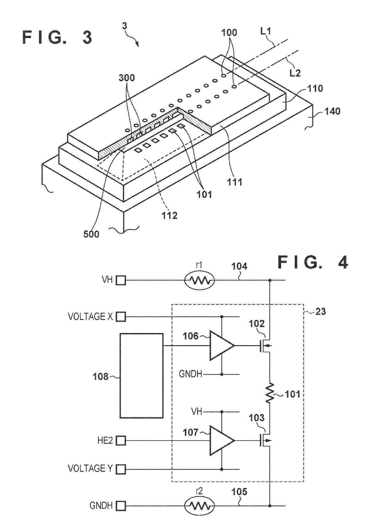
However, when many heaters are driven simultaneously, current flowing to the wiring increases.
As a result, there are cases where a voltage drop due to parasitic resistance of the wiring increases and it is impossible to generate the desired thermal energy in the heaters.
In other words, when the voltage applied to the drain of the transistor falls below the gate voltage, the voltage supplied to the heaters will not be fixed.
Accordingly, this leads to a bottleneck in acceleration because it becomes important to suppress heat within the printhead as much as possible from the perspective of throughput.

Method used


Image

  • Printing apparatus and method of controlling printhead
  • Printing apparatus and method of controlling printhead
  • Printing apparatus and method of controlling printhead

Examples


Embodiment Construction

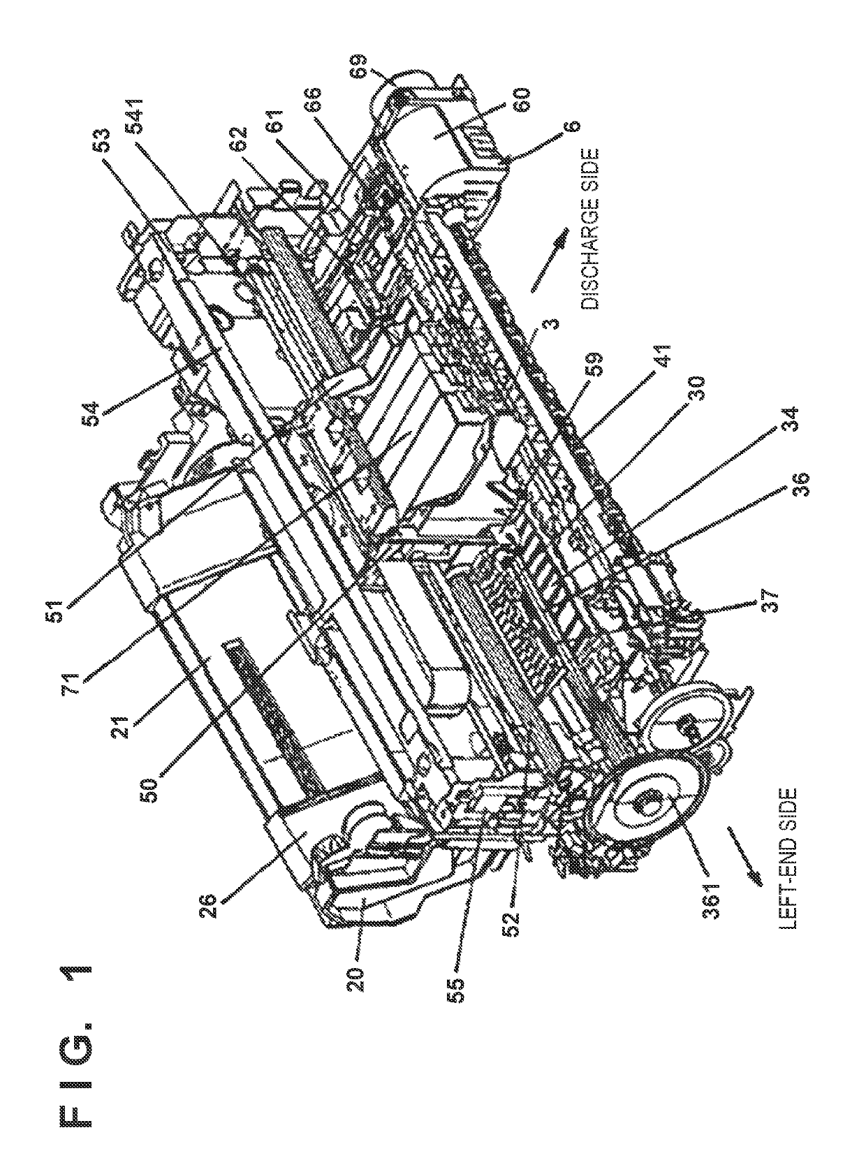
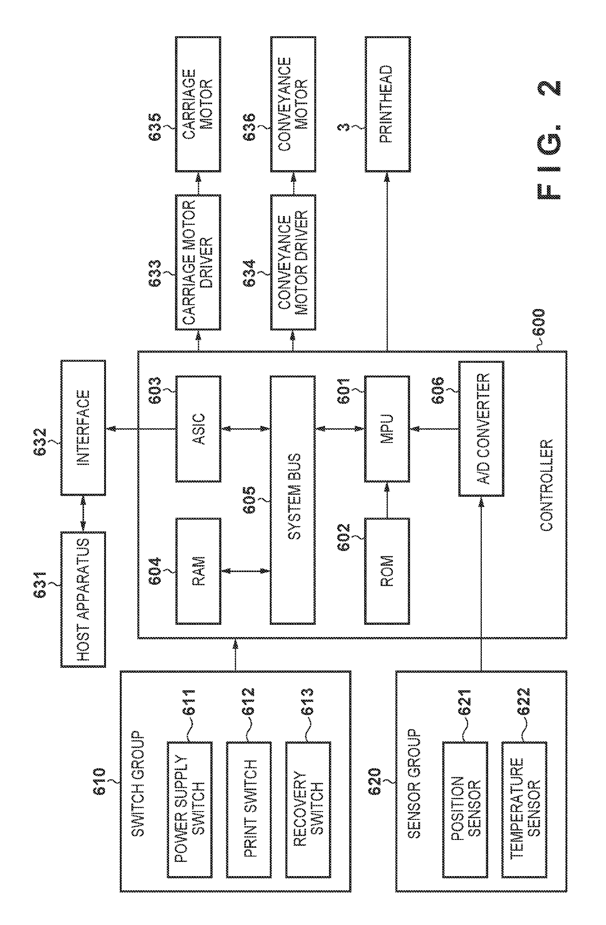
[0020]Hereinafter, description is given regarding an embodiment of the present invention with reference to the figures.

[0021]Below, more specific descriptions are given in detail for preferred embodiments of the present invention with reference to the attached drawings. However, relative arrangements of configuration elements, and the like, recited in this embodiment are not intended to limit the scope of the invention thereto, unless specifically stated.

[0022]Note that in this specification, “print” represents forming not only meaningful information such as characters and shapes, but also meaningless information. Furthermore, it is assumed that “print” broadly represents cases in which an image, design, or pattern is formed on a printing medium irrespective of whether or not it is something that a person can visually perceive, and cases in which a medium is processed.

[0023]Also, it is assumed that “printing medium” broadly represents not only paper used in a typical printing appara...


PUM


Abstract

A printing apparatus comprises: a plurality of printing elements; driving circuits that have at least one source follower transistor and correspond to each of the plurality of printing elements; and a control unit configured to, in a case where a number of printing elements driven simultaneously does not exceed a predetermined number, perform a first control for driving the at least one source follower transistor by a fixed pulse width irrespective of the number of printing elements driven simultaneously, and, in a case where the number of printing elements driven simultaneously exceed the predetermined number, perform a second control for changing a pulse width to drive the at least one source follower transistor based on the number of printing elements driven simultaneously.

Description

BACKGROUND OF THE INVENTIONField of the Invention[0001]The present invention relates to a printing apparatus and a method of controlling a printhead.Description of the Related Art[0002]In printing apparatuses that cause ink to discharge by heating the ink by energy generation elements (hereinafter referred to as heaters) arranged for discharge ports of a printhead, it is preferable to drive as many heaters as possible simultaneously in order to perform a print by the printhead at a high speed. However, when many heaters are driven simultaneously, current flowing to the wiring increases. As a result, there are cases where a voltage drop due to parasitic resistance of the wiring increases and it is impossible to generate the desired thermal energy in the heaters. Deterioration of image quality occurs because a variation of the thermal energy causes the volume of ink that is discharged to vary.[0003]In order to solve such a problem, in Japanese Patent Laid-Open No. H10-44416, for a vol...

Claims


Application Information

Patent Timeline
Patent Type & Authority Patents(United States)
IPC IPC(8): B41J29/38B41J2/045
CPCB41J2/04591B41J2/0455B41J2/0458B41J2/04598B41J2/04563B41J2/04568B41J2/04586B41J2/04541
Inventor MIURA, YOSUKETOMIZAWA, KEIJI
Owner CANON KK
Why Eureka
Try Eureka