Control circuit and device with edge comparison for switching circuit

a control circuit and switching circuit technology, applied in the field of circuits, can solve problems such as inability to compare edge comparisons, and inability to control circuits, and achieve the effects of reducing turn-on, increasing turn-on time, and reducing the turn-on tim

Active Publication Date: 2019-06-11
JOULWATT TECH INC LTD
View PDF10 Cites 2 Cited by
  • Summary
  • Abstract
  • Description
  • Claims
  • Application Information

AI Technical Summary

Benefits of technology

[0006]An objective of the present invention is to provide a control method, a control circuit and a device for a switching circuit, for realizing a function of fixing a frequency of the switching circuit which is operated under CCM, thus the application scope of the control method of the switching circuit is increased.
[0010]According to a third aspect, the disclosure further provides a control circuit for a switching circuit, the control circuit is used in the switching circuit operated under the continuous conduction mode, wherein the switching circuit comprises a first switch and transforms an input voltage into an output voltage for driving loads by turning the first switch on and off, and the control circuit comprises: a timing module, which starts time measuring at a rising edge of a turn-on signal of the first switch; a regulation module, which is connected with the timing module, used to reduce a turn-on time or a turn-off time of the first switch for fixing a frequency of the switching circuit when a first measured time is reached and the rising edge in a next cycle of the turn-on signal has not arrived, and used to increase the turn-on time or the turn-off time of the first switch for fixing the frequency of the switching circuit when the rising edge in the next cycle of the turn-on signal has arrived before the first measured time is reached.
[0017]According to a fourth aspect, the disclosure further provides a control circuit for a switching circuit, which is used to control the switching circuit operated under continuous conduction mode, the switching circuit comprises a first switch and transforms an input voltage into an output voltage for driving loads by turning the first switch on and off, the control circuit comprises: a timing module, which starts time measuring at a rising edge of a turn-on signal of the first switch; a regulation module, which is connected with the timing module, used to reduce a turn-on time or a turn-off time of the first switch when a first measured time is reached and the rising edge in a next cycle of the turn-on signal has not arrived, and used to increase the turn-on time or the turn-off time of the first switch when the rising edge in the next cycle of the turn-on signal has arrived before the first measured time is reached.
[0019]Compared with the prior art, the present invention has following beneficial effects: the control method for the switching circuit provided by the embodiment of the present disclosure includes the above steps, so that it is only needed to start time measuring at a rising edge of the turn-on signal of the first switch, to reduce the turn-on time or the turn-off time of the first switch for fixing the frequency of the switching circuit if the rising edge in the next cycle of the turn-on signal of the first switch has not arrived when the first measured time is reached, and to increase the turn-on time or the turn-off time of the first switch for fixing the frequency when the rising edge in the next cycle of the turn-on signal of the first switch has arrived before the first measured time is reached. Therefore, the relationship between the input voltage and the output voltage of the control method for the switching circuit provided by the embodiment of the present disclosure is not required to satisfy specific conditions for fixing the frequency of the switching circuit, which extends the application scope of the control method for the switching circuit provided by the embodiment of the present disclosure.

Problems solved by technology

However, the buck circuit in the prior art operated under CCM and working in the constant on-time control mode or the constant off-time control mode cannot realize a function for fixing a frequency, that is, cannot keep a switching frequency of the first switch 1′ at a constant value.

Method used


Image

  • Control circuit and device with edge comparison for switching circuit
  • Control circuit and device with edge comparison for switching circuit
  • Control circuit and device with edge comparison for switching circuit

Examples


first embodiment

A First Embodiment

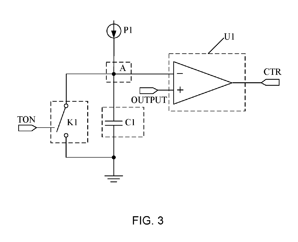
[0033]For solving the problems described in the background, the embodiment of the disclosure provides a device for a switching circuit, comprising a switching circuit and a control circuit, the control circuit is used to control a buck circuit operated under CCM and working in a constant on-time control mode. Specifically, as shown in FIG. 3, the control circuit comprises a first switch K1, a first capacitor C1, a first current source P1 and a first voltage comparator U1, a control terminal of the first switch K1 receives a turn-on signal TON of the first switch, a first terminal of the first switch K1 is grounded, a node connected with a second terminal of the first switch K1 is marked as a first node A, the first node A is further connected with the first current source P1, a first electrode of the first capacitor C1 and a first input terminal of the first voltage comparator U1, respectively, a second electrode of the first capacitor C1 is grounded, a second inpu...

second embodiment

A Second Embodiment

[0039]According to the calculation process for obtaining the switching cycle Ta of the turn-on signal of the first switch in the first embodiment, it can be known that the condition for satisfying the second equation by the input voltage Vin of the buck circuit and the output voltage Vout of the buck circuit is to use a buck circuit as the switching circuit, to control the buck circuit in the constant on-time control mode and to operate under CCM. However, besides the buck circuit, the switching circuit can also be a boost circuit, a flyback circuit, a buck-boost circuit or other circuits in different types.

[0040]The inventor of the disclosure finds that, when the switching circuit is not a buck circuit, the input voltage and the output voltage of the switching circuit cannot satisfy the second equation, and even if the switching circuit is a buck circuit, when the switching circuit works in the constant off-time control mode and is operated under CCM, the input v...

third embodiment

A Third Embodiment

[0045]The embodiment of the present disclosure provides a device for the switching circuit comprising a switching circuit and a control circuit, the control circuit is used for the switching circuit operated under continuous conduction mode, the switching circuit comprises a first switch and transforms an input voltage into an output voltage for driving a load by turning the first switch on and off. As shown in FIG. 6, the control circuit comprises a time module 1, which starts time measuring at a rising edge of a turn-on signal of the first switch, and a regulation module 2 connected with the timing module 1, which is used to reduce a turn-on time or a turn-off time of the first switch for fixing a frequency of the switching circuit if the rising edge in a next cycle of the turn-on signal has not arrived when a first measured time is reached and to increase the turn-on time or the turn-off time of the first switch for fixing the frequency of the switching circuit ...


PUM


Abstract

A control method, a control circuit and a device for a switching circuit are disclosed, for fixing a frequency of the switching circuit when the switching circuit is operated under CCM. The present disclosure is suitable to various switching circuits, and an application scope of the control method of the switching circuit can be extended. The control method comprises: starting measuring time at a rising edge of a turn-on signal of the first switch; reducing a turn-on time or a turn-off time of the first switch when a first measured time is reached, and the rising edge in a next cycle of the turn-on signal has not arrived; increasing the turn-on time or the turn-off time of the first switch when the rising edge in the next cycle of the turn-on signal arrives but the first measured time is not reached.

Description

CROSS-REFERENCE TO RELATED APPLICATION[0001]This application claims the benefit of Chinese Patent Application No. 201610790138.5, filed on Aug. 31, 2016, which is incorporated herein by reference in its entirety.BACKGROUND OF THE DISCLOSUREField of the Disclosure[0002]The present disclosure relates to the technical field of circuits, and more particularly, to a control method, a control circuit and a device for a switching circuit.Background of the Disclosure[0003]At present, a switching circuit (such as a buck circuit which is used to obtain a voltage drop) is a common circuit used in circuit design, for example, as shown in FIG. 1, a buck circuit generally comprises a first switch 1′, a second switch 2′ and an inductor 3′, wherein the first switch 1′ may be a MOSFET (Metal Oxide Semiconductor Field Effect Transistor), the second switch 2′ may be a freewheel diode or a synchronous rectifier, Vin′ is an input voltage of the buck circuit, Vout′ is an output voltage of the buck circui...

Claims


Application Information

Patent Timeline
Patent Type & Authority Patents(United States)
IPC IPC(8): H02M3/156H02M3/157H02M1/00
CPCH02M3/156H02M2001/0012H02M3/157H02M3/1582H02M1/0012
Inventor WONG, PITLEONGXU, FENGCHAN, SIOPANGREN, YUANCHENGZHOU, XUNWEI
Owner JOULWATT TECH INC LTD
Why Eureka
Try Eureka