
Membrane-seal assembly

a membrane and assembly technology, applied in the direction of electrochemical generators, electrical apparatus, fuel cells, etc., can solve the problems of subsequent membrane, mea and fuel cell failure, and considerable durability, and achieve the effect of improving the durability and lifetime of mea

Active Publication Date: 2019-06-25
JOHNSON MATTHEY HYDROGEN TECH LTD
View PDF23 Cites 0 Cited by
  • Summary
  • Abstract
  • Description
  • Claims
  • Application Information

AI Technical Summary

Benefits of technology

[0013]Therefore, even with state-of-the-art reinforced membranes, there is still the need to improve the durability and lifetime of the MEA when used in a fuel cell.

Problems solved by technology

With these conventional MEA constructions involving the use and bonding together of separate sealing films and ion-conducting membranes or catalyst coated ion-conducting membranes there remain considerable durability issues for the MEA due, for example, to the mechanical stresses that can be built up in the membrane and at the edges of the MEA where the seal overlaps the membrane, due to the dimensional changes that still occur within the conventional reinforced membranes on hydration and dehydration as the operational conditions of the fuel cell changes.
These stresses cause a weakness in the membrane at these points that leads to tearing of the membrane in the edge regions close to the interface with the seal layer and subsequent membrane, MEA and fuel cell failure.

Method used


Image

  • Membrane-seal assembly
  • Membrane-seal assembly
  • Membrane-seal assembly

Examples


Embodiment Construction

[0024]Preferred and / or optional features of the invention will now be set out. Any aspect of the invention may be combined with any other aspect of the invention, unless the context demands otherwise. Any of the preferred or optional features of any aspect may be combined, singly or in combination, with any aspect of the invention, unless the context demands otherwise.

[0025]The invention provides a reinforced membrane-seal assembly comprising a reinforcing component, an ion-conducting material and a seal component.

[0026]The reinforcing component is planar and comprises a first surface and an opposing second surface.

[0027]The reinforcing component suitably has a thickness of from 5-100 μm, suitably 5-50 μm, and preferably 5-20 μm.

[0028]The planar dimensions (x / y dimensions) of the reinforcing component will be dependent upon the final use of the reinforced membrane-seal assembly and determinations thereof are within the capability of the skilled person. The x and y dimensions are not...


PUM

PropertyMeasurementUnit
areaaaaaaaaaaa
widthaaaaaaaaaa
widthaaaaaaaaaa

Abstract

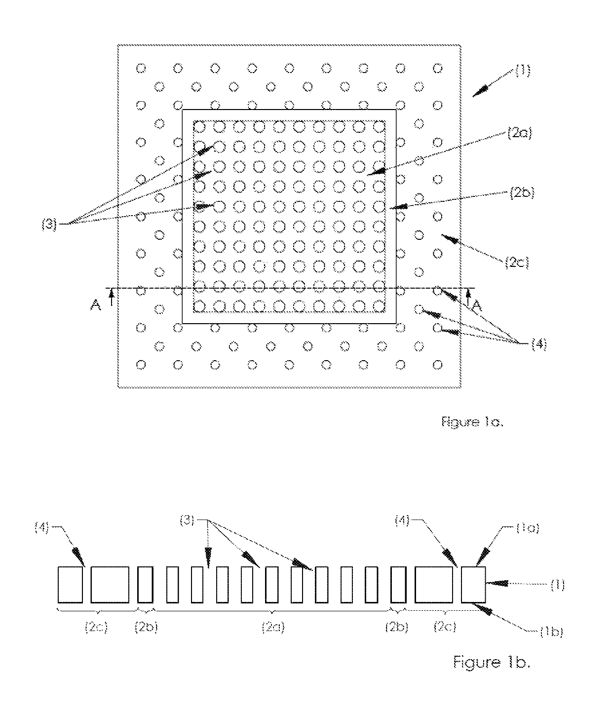
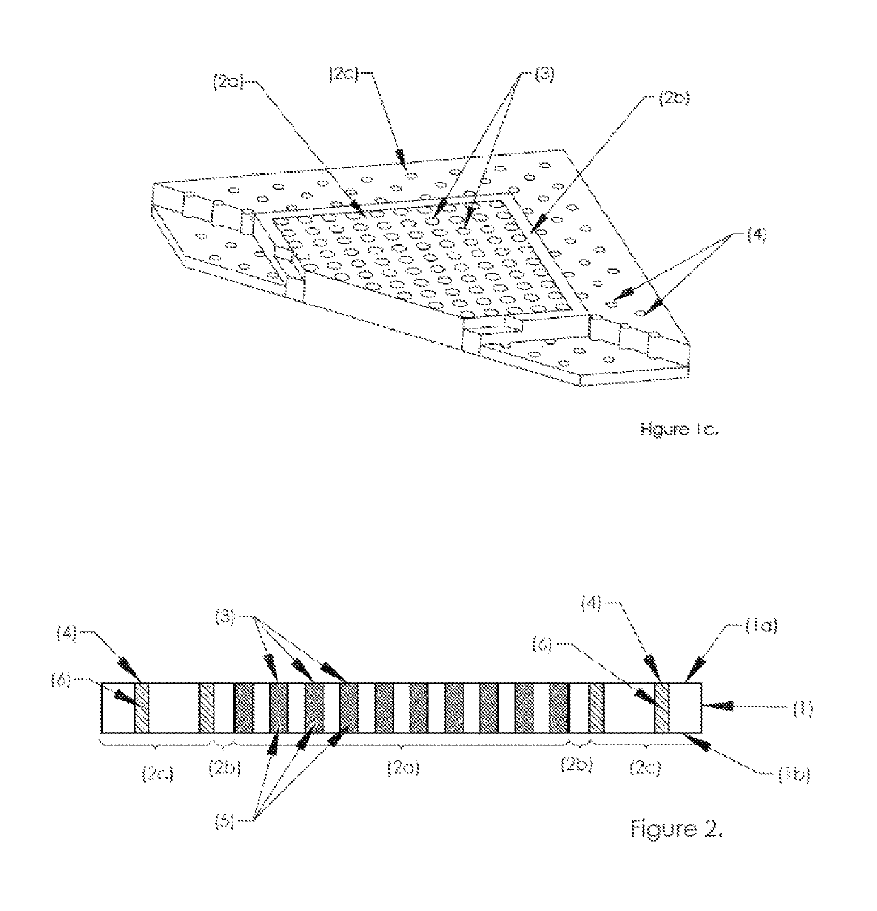
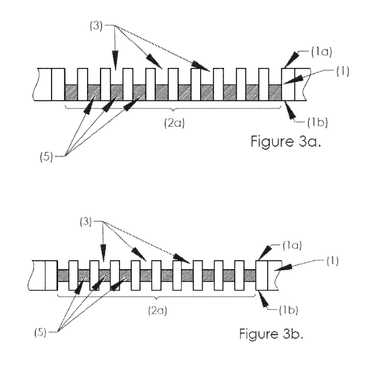
The invention includes a reinforced membrane-seal assembly that comprises a reinforcing component, ion-conducting material, and seal material. The reinforcing component comprises a central region comprising a plurality of apertures extending from a first surface to a second surface of the reinforcing component, the central region having a first aperture area density; an inner peripheral border region surrounding the central region, where the inner peripheral border region is devoid of apertures; and an outer peripheral border region comprising a plurality of apertures extending from the first surface to the second surface of the reinforcing component, the outer peripheral border region having a second aperture area density. The outer peripheral border region surrounds the inner peripheral border region. The ion-conducting material at least partially fills each aperture in the central region of the reinforcing component and seal material fills each aperture in the outer peripheral border region of the reinforcing component.

Description

FIELD OF THE INVENTION[0001]The present invention relates to a reinforced membrane-seal assembly and its use in an electrochemical device, in particular its use in a proton exchange membrane fuel cell.BACKGROUND OF THE INVENTION[0002]A fuel cell is an electrochemical cell comprising two electrodes separated by an electrolyte. A fuel, e.g. hydrogen, an alcohol such as methanol or ethanol, or formic acid, is supplied to the anode and an oxidant, e.g. oxygen or air, is supplied to the cathode. Electrochemical reactions occur at the electrodes, and the chemical energy of the fuel and the oxidant is converted to electrical energy and heat. Electrocatalysts are used to promote the electrochemical oxidation of the fuel at the anode and the electrochemical reduction of oxygen at the cathode.[0003]Fuel cells are usually classified according to the nature of the electrolyte employed. Often the electrolyte is a solid polymeric membrane, in which the membrane is electronically insulating but io...

Claims


Application Information

Patent Timeline
Patent Type & Authority Patents(United States)
IPC IPC(8): H01M8/0271H01M8/1004H01M8/1018H01M8/1062H01M8/1065H01M8/00
CPCH01M8/0271H01M8/1004H01M8/1065H01M8/1062H01M2008/1095H01M8/00Y02E60/50
Inventor COLEMAN, ROBERT JEFFREYO'SULLIVAN, JULIEDICKINSON, ANGUS
Owner JOHNSON MATTHEY HYDROGEN TECH LTD
Learn More