
Air conditioner

a technology for air conditioners and air conditioners, applied in the field of air conditioners, can solve the problems of insufficient cooling ability, insufficient cooling ability of refrigerant flowing in the indoor unit, and difficulty in obtaining sufficient cooling ability, and achieve the effect of sufficient heating ability

Active Publication Date: 2019-07-02
FUJITSU GENERAL LTD
View PDF18 Cites 2 Cited by
  • Summary
  • Abstract
  • Description
  • Claims
  • Application Information

AI Technical Summary

Benefits of technology

[0012]The present invention solves the above-mentioned problem, and an object thereof is to provide an air conditioner capable of displaying sufficient heating ability at each indoor unit at the time of heating operation even when the outdoor unit is installed in a higher position than a plurality of indoor units.
[0013]To solve the above-mentioned problem, an air conditioner of the present invention is provided with: an outdoor unit having a compressor and discharge pressure detector configured to detect a discharge pressure which is a pressure of a refrigerant discharged from the compressor, and a plurality of indoor units each having an indoor heat exchanger, an indoor expansion valve and liquid side temperature detector configured to detect a heat exchange exit temperature which is a temperature of the refrigerant flowing out from the indoor heat exchanger when the indoor heat exchanger is functioning as a condenser, and the outdoor unit is installed above the plurality of indoor units and there is a difference in height between installation places of the plurality of indoor units. And controller is provided for executing a refrigerant amount balance control to adjust degrees of opening of the indoor expansion valves so that refrigerant supercooling degrees of the indoor units become an average refrigerant supercooling degree obtained by using a maximum value and a minimum value of the refrigerant supercooling degrees or that the heat exchange exit temperatures of the indoor units become an average heat exchange exit temperature obtained by using a maximum value and a minimum value of the heat exchange exit temperatures when the air conditioner performs heating operation.

Problems solved by technology

Since the amount of refrigerant flowing through the indoor expansion valve decreases as the difference in pressure between on the upstream side and on the downstream side of the indoor expansion valve decreases, a large amount of refrigerant flows in the indoor unit installed in the lower position, whereas the amount of refrigerant flowing in the indoor unit installed in the higher position decreases and there is a possibility that sufficient cooling ability is not obtained.
When heating operation is performed by an air conditioner where indoor units are installed with a difference in height therebetween and an outdoor unit is installed in a higher position than the indoor units unlike the air conditioner of JP-A-4-28970, a problem described below arises.
In heating operation, while the gas refrigerant discharged from the compressor flows into the indoor heat exchanger of each indoor unit to be condensed, since the liquid refrigerant condensed at the indoor heat exchanger and having flown into the liquid pipe flows against gravity toward the outdoor unit installed in the higher position, the lower the position in which an indoor unit is installed is, the more difficult it is for the liquid refrigerant having flown from the indoor unit into the liquid pipe to flow toward the outdoor unit.
Since the amount of refrigerant flowing through the indoor expansion valve decreases as the difference between the refrigerant pressure on the upstream side of the indoor expansion valve and the refrigerant pressure on the downstream side thereof decreases, a large amount of refrigerant flows in the indoor unit installed in the higher position, whereas the amount of refrigerant flowing in the indoor unit installed in the lower position decreases and there is a possibility that sufficient heating ability is not obtained in the indoor unit.
However, the difference in height between the indoor unit installed in the lower position and the indoor unit installed in the higher position is large, and the liquid refrigerant having flown from the indoor unit installed in the lower position into the liquid pipe does not flow toward the outdoor unit; that is, when the liquid refrigerant stays below the liquid pipe, even if the degree of opening of the indoor expansion valve of the indoor unit installed in the lower position is made full opening, no refrigerant flows in the indoor unit and no heating ability is displayed (heating cannot be performed).

Method used


Image

  • Air conditioner
  • Air conditioner
  • Air conditioner

Examples


first embodiment

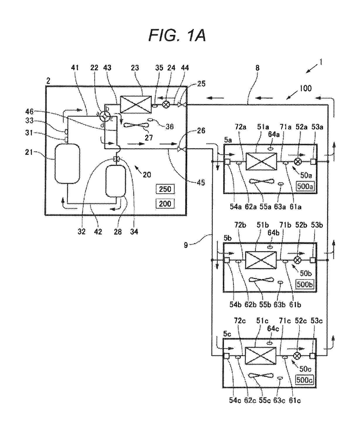
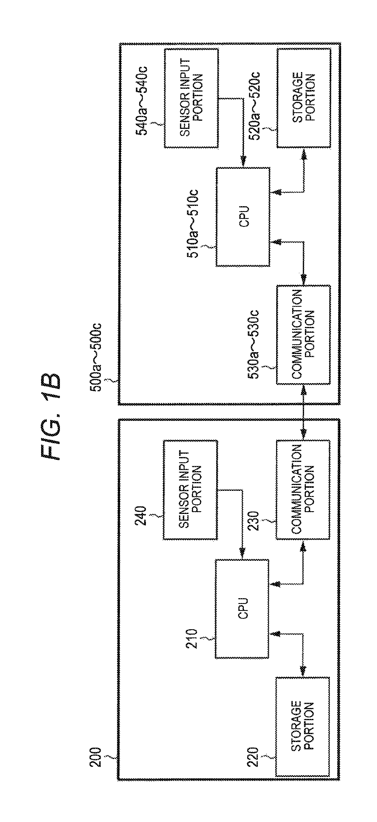
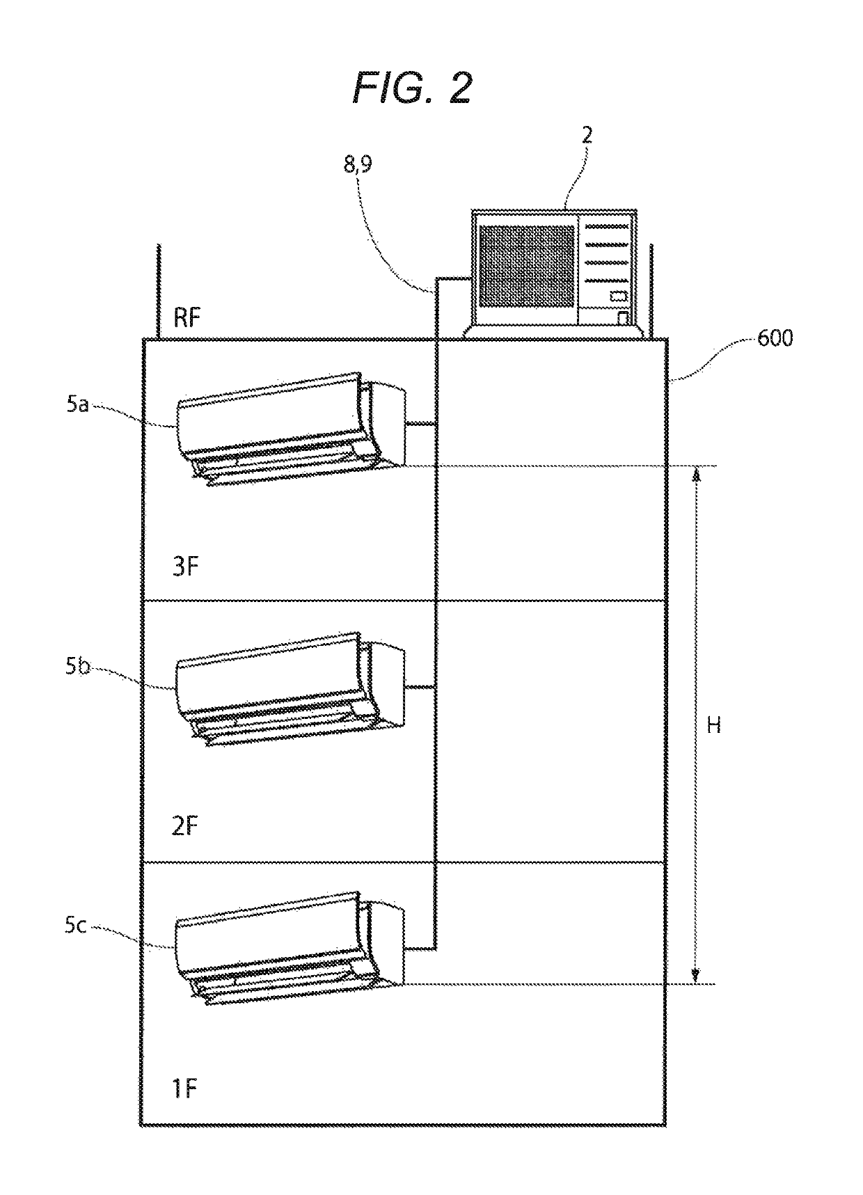
[0021]As shown in FIG. 1A and FIG. 2, an air conditioner 1 of the present embodiment is provided with one outdoor unit 2 installed on the roof of a building and three indoor units 5a to 5c installed on the floors of the building, respectively, and connected in parallel to the outdoor unit 2 by a liquid pipe 8 and a gas pipe 9. Specifically, the liquid pipe 8 has its one end connected to a closing valve 25 of the outdoor unit 2 and has its other end branched to be connected to liquid pipe connection portions 53a to 53c of the indoor units 5a to 5c. The gas pipe 9 has its one end connected to a closing valve 26 of the outdoor unit 2 and has its other end branched to be connected to gas pipe connection portions 54a to 54c of the indoor units 5a to 5c. This constitutes a refrigerant circuit 100 of the air conditioner 1.

[0022]First, the outdoor unit 2 will be described. The outdoor unit 2 is provided with a compressor 21, a four-way valve 22, an outdoor heat exchanger 23, an outdoor expa...

second embodiment

[0076]Next, a second embodiment of the present invention will be described by using mainly FIG. 4. What is different from the first embodiment is that in the second embodiment, the refrigerant amount balance control is executed from the point of time when it is determined that there is an indoor unit where heating ability is not displayed whereas in the first embodiment, the refrigerant amount balance control is executed from the time of start of heating operation (precisely, from when the refrigerant circuit 100 is stabilized). Detailed description of points other than this, that is, the components of the air conditioner 1 and the state of the refrigerant circuit 100 at the time of heating operation is omitted since it is the same as that of the first embodiment.

[0077]As described in the first embodiment, if the refrigerant amount balance control is executed, in the indoor unit where the refrigerant supercooling degree is higher than the average refrigerant supercooling degree of t...


PUM


Abstract

When a refrigerant amount balance control is executed, in indoor units where the refrigerant supercooling degree is lower than an average refrigerant supercooling degree, the refrigerant pressure on a downstream side of indoor expansion valves decreases since the degrees of opening of the valves are decreased. On the other hand, in an indoor unit where the refrigerant supercooling degree is higher than the average refrigerant supercooling degree, although the degrees of opening of the valves are made high, the refrigerant pressure on the downstream side of the valves decreases and this decreases the refrigerant pressure on the downstream side of the indoor expansion valve, so that the difference in pressure between on the upstream side and on the downstream side of the indoor expansion valve increases and the liquid refrigerant staying at an indoor heat exchanger of the indoor unit consequently flows out into a liquid pipe.

Description

CROSS-REFERENCE TO RELATED APPLICATION[0001]The present application claims the benefit of priority of Japanese Patent Application No. 2016-002698, filed on Jan. 8, 2016, which is incorporated herein by reference.TECHNICAL FIELD[0002]The present invention relates to an air conditioner where a plurality of indoor units are connected to at least one outdoor unit by refrigerant pipes.BACKGROUND ART[0003]Air conditioners are known where a plurality of indoor units are connected to at least one outdoor unit by a liquid pipe and a gas pipe. Among such air conditioners, an air conditioner has been proposed where sufficient air conditioning ability can be displayed at each indoor unit by controlling a refrigerant circuit in consideration of the difference in height between the installation place of the outdoor unit and the installation places of the indoor units and the difference in height between the indoor units.[0004]For example, in an air conditioner described in JP-A-4-28970, an outdoo...

Claims


Application Information

Patent Timeline
Patent Type & Authority Patents(United States)
IPC IPC(8): F25B13/00F25B49/02
CPCF25B13/00F25B49/02F25B2313/0233F25B2313/0292F25B2313/02334F25B2600/19F25B2700/21175F25B2700/1931F25B2700/1933F25B2700/21151F25B2700/21152F25B2700/21163F25B2600/2513F25B5/02F25B29/003
Inventor OKA, YASUHIROTOMIOKA, SATOSHISHIMOTANI, MAKOTOMATSUNAGA, TAKAHIRO
Owner FUJITSU GENERAL LTD
Learn More