
Panel carrier

a panel and carrier technology, applied in the field of woodworking and construction industry, can solve the problems of heavy weight, difficult handling, heavy weight, etc., and achieve the effect of easy picking up and moving a panel

Active Publication Date: 2019-07-09
AFFINITY TOOL WORKS
View PDF63 Cites 4 Cited by
  • Summary
  • Abstract
  • Description
  • Claims
  • Application Information

AI Technical Summary

Benefits of technology

[0007]In general terms, this invention provides a panel carrier that can support a panel for transport to for example a work station, and when in place, be pivoted to support the panel in either a vertical position or horizontal position for further work. The panel carrier allows a single person to easily pick up and move a panel and then position and hold the panel as the user works with the panel.
[0011]An adjustable support member is also provided to interconnect the support surface to the frame. This adjustable support member allows the support surface to be adjusted with respect the fame to enable the height of the panel in the working position to be adjusted to a desired height.

Problems solved by technology

These sheets are bulky and heavy, making them difficult to handle.
As can be appreciated, the size and weight of these sheets make them very difficult to handle.
Moving the panels from a workplace is difficult and typically requires two people.
None of these are desirable alternatives.
Again, not a desired way of handling sheets of material

Method used


Image

  • Panel carrier
  • Panel carrier
  • Panel carrier

Examples


Embodiment Construction

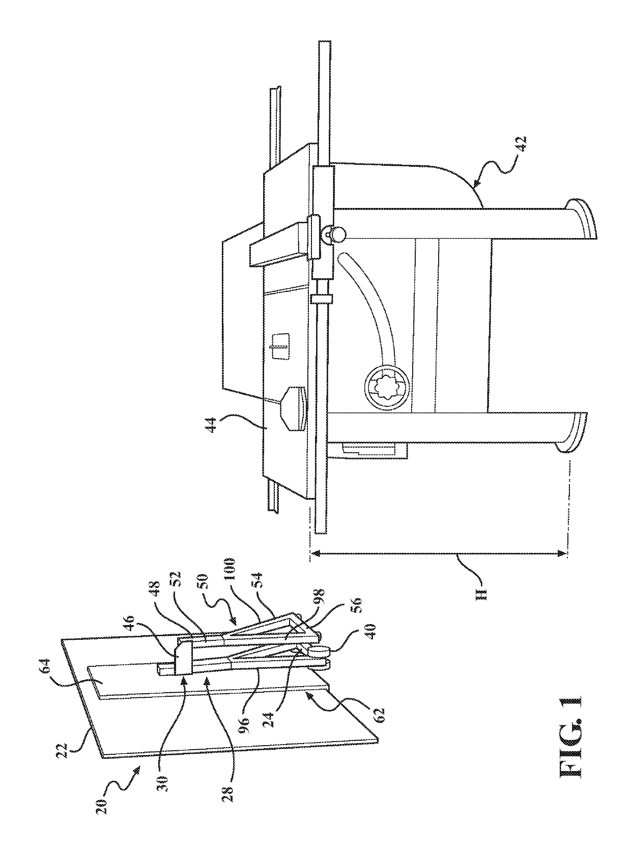
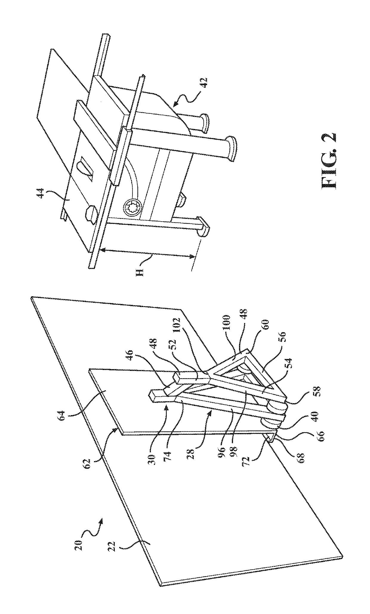
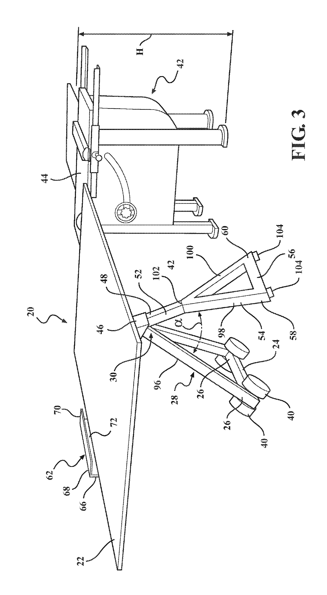
[0024]Referring to the Figures, wherein like numerals indicate corresponding parts throughout the several views, a panel carrier apparatus 20 for moving a panel 22 along a surface is generally shown in FIGS. 1 through 6.

[0025]The apparatus 20 includes a base 24 extending between a pair of base ends 26 and a frame 28, as generally indicated. The base 24, the base ends 26 and the frame 28 as illustrated are made of rectangular shaped tubing, but it will be understood by those of ordinary skill in the art that the tubing could be circular in cross section, triangular, etc., and hollow or solid.

[0026]The frame 28 extends outwardly from the base 24 to an apex 30. With reference to FIG. 7, the frame 28 has a front face 32 and a back face 34 and a pair of side faces 36. A support rod or arm 38 having a rectangular shape as illustrated is mounted within the frame 28. A pair of wheels 40 are mounted at each of the base ends 26 of the base 24 for moving the frame 28 along a surface to for exa...


PUM

PropertyMeasurementUnit
movementaaaaaaaaaa
thicknessesaaaaaaaaaa
thicknessaaaaaaaaaa

Abstract

The present invention is panel carrier for transporting and supporting a panel. The panel carrier includes a frame and a support leg pivotally mounted to the frame. The leg is pivotal between a transport position and a working position. A support surface is provided and is pivotally mounted to the frame. The support surface is pivotal between a transport position and a working position. A panel can be positioned upon the support surface when the support surface and the support leg are in the transport position and thereafter, the support surface and the support leg can be pivoted to the working position to support the panel generally perpendicular to the frame.

Description

RELATED APPLICATIONS[0001]This application claims the benefit of U.S. Provisional Application No. 61 / 904,585 filed on Nov. 15, 2013.STATEMENT REGARDING FEDERALLY SPONSORED RESEARCH[0002]None.TECHNICAL FIELD[0003]This invention relates generally to the woodworking and construction industry and more particularly to an inexpensive, compact carrier to carry and support large panels of material such as for example, sheets of plywood, particle board, drywall, etc. so that they can be moved with minimal effort and supported for processing functions, such as for example cutting, ripping, drilling, nailing etc.BACKGROUND OF THE INVENTION[0004]Large sheets of material, such as plywood, sheet rock, gypsum board, flooring, glass, mirrors, etc. are regularly used in all types of construction. These sheets are bulky and heavy, making them difficult to handle. Plywood for example is typically sold in 4 by 8 foot sheets and can have various thicknesses such as for example ¼″, ⅜″, ½″, ⅝″, ¾″ and 1″....

Claims


Application Information

Patent Timeline
Patent Type & Authority Patents(United States)
IPC IPC(8): B25H1/04B65G7/12B25H1/16B23D59/00
CPCB25H1/16B25H1/04B23D59/00
Inventor BRANSFORD, RUSSELL
Owner AFFINITY TOOL WORKS
Learn More