Tubular membrane with a helical ridge, as well as a method and apparatus for producing such a tubular membrane

a tubular membrane and helical ridge technology, applied in the field of tubular membranes, can solve the problems of only drawing coil inserts, cake accumulation along the membrane layer, and poor filtration performance of such tubular membranes, and achieve the effect of promoting local turbulence and secondary flow

Active Publication Date: 2019-09-03
X FLOW
View PDF4 Cites 1 Cited by
  • Summary
  • Abstract
  • Description
  • Claims
  • Application Information

AI Technical Summary

Benefits of technology

[0015]Since the ridge is covered with or forms part of the membrane layer, it advantageously has got the same surface properties as the remaining smooth surface of the membrane layer and thus does not restrict permeation or retention of the membrane.
[0018]The adding of such a helical ridge to this type of helically wound tubular membranes has appeared to result in the occurrence of turbulences and secondary flows just in front and behind the helical ridges. Those turbulences and secondary flows help to keep the boundary layer well mixed with the rest of the fluid flowing through the tubular membrane. The occurrence of the turbulences and secondary flows inside the boundary layer at the surface of the membrane layer leads to a thinner boundary layer, to less concentration polarization and less cake formation. This enables higher permeate fluxes compared to smooth cylindrical membranes without such helical ridges, albeit at the cost of a somewhat higher pressure drop. In fact it has even appeared that the performances of this type of helically wound tubular membranes can be increased with more than 50%. Such higher operational fluxes may lead to important capital savings due to less membrane area being required and / or may also contribute to a lower specific energy consumption (kWh per cubic meter of treated fluid) during filtration. Those advantages have appeared to go for the entire range of tubular membrane based filtration, from microfiltration, ultrafiltration, nanofiltration to reverse osmosis, they all may benefit from the invention.
[0019]In a particular embodiment the helical ridge has been made out of porous or semi-permeable material. This has the advantage that not only the surface properties of the ridge are the same as the membrane layer, but that the permeate is able to flow through the entire ridge. The ridge thus does not form an obstacle for the permeate flow itself.
[0024]In a particular embodiment the ridge during its forming, gets guided through one or more helical grooves in the mandrel. This advantageously makes it possible to use one and the same mandrel for the production process.
[0027]In a second embodiment the ridge is formed by a flexible ribbon-shaped ridge which is helically wound together with the tape(s) around the winding section of the mandrel. This ribbon-shaped ridge preferably is made of porous material. For this second embodiment the ribbon-shaped ridge may either be already present on and connected to the tape and thus automatically get helically wound together with the tape around the winding section of the mandrel, either be supplied as separate part to the winding section of the mandrel and there get helically wound together with the tape and sealed to the tape. During this helically winding of the ribbon-shaped ridge together with the tape around the winding section of the mandrel, the ribbon-shaped ridge gets the freedom to run through a helical groove which is provided in the winding section of the mandrel.

Problems solved by technology

The most significant limitations to filtration performances of such tubular membranes are concentration polarization near the membrane layer, the buildup of a cake along the membrane layer and fouling of the membrane layer.
The use of such helical coil inserts however has the disadvantage that the coil inserts can only be drawn through tubular membranes after first having been elastically stretched to such an extent that they have become more slender than the inner diameter of the tubular membranes themselves.
As one can imagine this is a time-consuming and difficult operation which cannot be performed in large numbers on an industrial scale, particularly for smaller diameter membrane tubes.
A disadvantage hereof is that a relative complex extrusion process is needed.
Furthermore it is limited to ceramic support tubes, which are relative expensive to manufacture.
Finally it appeared that only gradually sloping corrugations could be obtained as relief stamp at the membrane surface with this manufacturing method, leading to only a limited reduction of the boundary layers and thus only to a limited increase in performances.

Method used


Image

  • Tubular membrane with a helical ridge, as well as a method and apparatus for producing such a tubular membrane
  • Tubular membrane with a helical ridge, as well as a method and apparatus for producing such a tubular membrane
  • Tubular membrane with a helical ridge, as well as a method and apparatus for producing such a tubular membrane

Examples


second embodiment

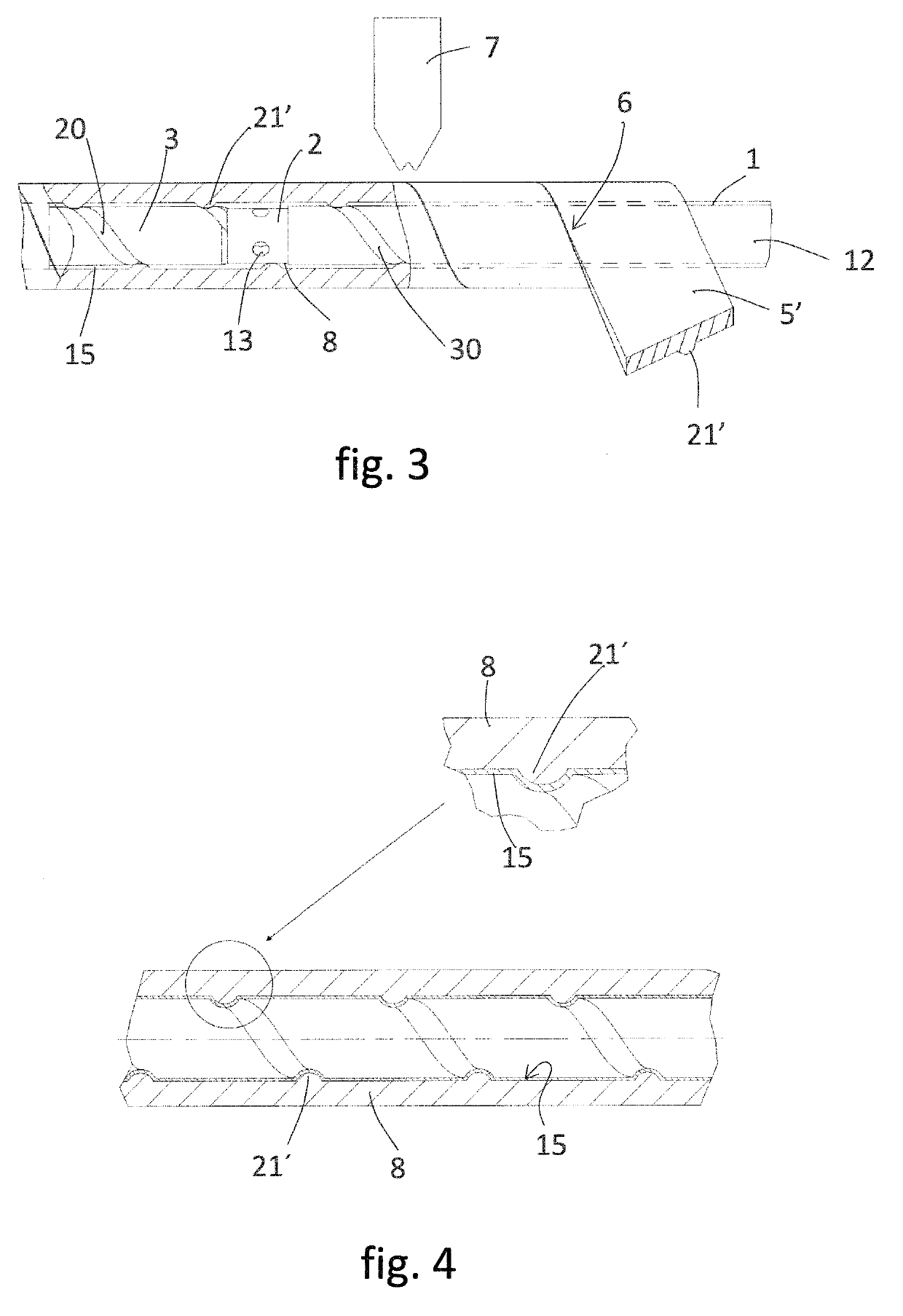
[0047]In FIG. 3 a second embodiment is shown of the apparatus in which similar parts have been given the same reference numerals. This time a tape 5′ is supplied to the winding section 1 which already comprises an integrally connected or formed ridge 21′ on it. This ridge 21′ is made out of the same or a similar type of porous material as the rest of the tape 5′. Furthermore in FIG. 3 the winding section 1 is provided with a downstream helical groove 30.

[0048]During winding, the ridge 21′ gets to run through the downstream helical groove 30 and thus gets helically wound along with the rest of the tape 5′ around the winding section 1 into the tube shaped support tube 8. When the support tube 8 with its integral ridge 21′ subsequently passes along the casting section 2 and doctoring section 3, the membrane layer 15 gets cast and doctored with a uniform layer thickness onto both the inner wall of the support tube 8 as well as onto the ridges 21′. This can be seen in FIG. 4.

[0049]The pi...

third embodiment

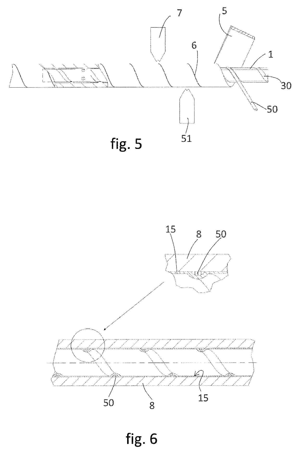
[0050]In FIG. 5 a third embodiment is shown. This time the tape 5 is supplied together with a distinctive separate ribbon-shaped ridge 50 towards the winding section 1. This ribbon-shaped ridge 50 is made of a similar type of porous material as the tape 5. During winding the ribbon-shaped ridge 50 gets to run through the downstream helical groove 30. At the winding section 1 now not only the overlapping tape edges 6 get sealed to each other by first sealing means 7, but also the ribbon-shaped ridge 50 gets sealed to the tape 5 by second sealing means 51. For its casting and doctoring section the apparatus of FIG. 5 is kept the same as in FIG. 3. In FIG. 6 the tubular membrane can be seen which is produced with the apparatus of FIG. 5.

fourth embodiment

[0051]In FIG. 7 a fourth embodiment is shown. This time no helical grooves are provided in the mandrel. Instead at the free end of the doctoring section a nozzle / outlet opening 70 is provided which connects to the channel 12 for feeding pressurized membrane forming material to the nozzle / outlet opening 70. When the forward moving rotating support tube 8 with its already casted and doctored membrane layer 15 passes this nozzle / outlet opening 70, an inwardly projecting ridge gets automatically formed onto the membrane layer 15. By subsequently curing, leaching and / or drying the thus formed tubular membrane, a similar type as shown in FIG. 2 can be obtained, that is to say one with a semi-permeable helical ridge of membrane forming material inside a helically wound support tube.

[0052]Besides the above four embodiments numerous variants are possible. For example the dimensions and shapes of the helical ridge can easily be varied. The profile of the ridge can for example be made triangul...


PUM

PropertyMeasurementUnit
thicknessaaaaaaaaaa
diametersaaaaaaaaaa
diametersaaaaaaaaaa

Abstract

A tubular membrane includes a support tube made out of one or more flexible tapes of porous support material which have been helically wound into a tube shape with overlapping tape edges which have been sealed to each other, and a semi-permeable membrane layer made of membrane forming material on an inner wall of the support tube. At least one inwardly projecting helical ridge is provided on the inner wall of the support tube, which helical ridge is covered with or forms part of the membrane layer.

Description

CROSS-REFERENCE TO RELATED APPLICATIONS[0001]This application is the National Stage of International Application No. PCT / NL2015 / 050016 filed Jan. 12, 2015, which claims the benefit of Netherlands Application No. NL 2012109, filed Jan. 20, 2014, the contents of which is incorporated by reference herein.FIELD OF THE INVENTION[0002]The invention relates to the field of tubular membranes of the type comprising a support tube which is built up out of one or more flexible tapes of porous support material which have been helically wound into a tube shape with overlapping tape edges which have been sealed to each other, and with a semi-permeable membrane layer made of membrane forming material on an inner wall of the support tube. This specific type of tubular membrane shall be referred to as helically wound tubular membrane.BACKGROUND OF THE INVENTION[0003]Such helically wound tubular membranes as well as a method and apparatus for producing them are known from for example GB-1 325 672. Th...

Claims


Application Information

Patent Timeline
Patent Type & Authority Patents(United States)
IPC IPC(8): B01D63/06B29C53/58B29C65/08B29C53/82B29C41/20B29K67/00B29K105/04B29L31/14
CPCB01D63/061B01D63/063B29C65/08B29C53/821B29C41/20B29C53/585B29L2031/14B29K2067/00B29K2105/04B01D63/06B29C53/58B29C53/82
Inventor OBORNÝ, RADEKKOEL, STEFANPOTRECK, JENSOBORN, RADEK
Owner X FLOW
Why Eureka
Try Eureka