Vehicle Energy Harvesting System

Inactive Publication Date: 2019-02-07
EPITOME PROPERTY INVESTMENTS PTY LTD
View PDF33 Cites 7 Cited by
  • Summary
  • Abstract
  • Description
  • Claims
  • Application Information

AI Technical Summary

Benefits of technology

The invention is a system for harvesting energy from vehicles driving on a road. The system includes tubular members embedded in the road or placed on top of the road, which contain energy transfer fluid. When a vehicle passes over the tubular members, the fluid is compressed or displaced, and this pressure is converted into electrical power by a double-acting fluid cylinder. The system also includes a drivetrain and an energy converting means to convert the fluid's motion into electrical energy. The system can be controlled to regulate the amount of fluid displaced and can be replenished with new fluid. The technical effect of this invention is to provide a sustainable energy source for vehicles on the road, which can help reduce energy waste and promote energy efficiency.

Problems solved by technology

These systems, although effective in contributing to power in our electricity grids, often do not come without problems.
Very often these traditional systems are made from complicated technology and some of them are effective only when certain atmospheric parameters are met or conditions are suitable.

Method used


Image

  • Vehicle Energy Harvesting System
  • Vehicle Energy Harvesting System
  • Vehicle Energy Harvesting System

Examples


Embodiment Construction

[0034]The following description of the invention is provided as an enabling teaching of the invention. Those skilled in the relevant art will recognise that many changes can be made to the embodiment described, while still attaining the beneficial results of the present invention. It will also be apparent that some of the desired benefits of the present invention can be attained by selecting some of the features of the present invention without utilising other features. Accordingly, those skilled in the art will recognise that modifications and adaptations to the present invention are possible and can even be desirable in certain circumstances, and are a part of the present invention. Thus, the following description is provided as illustrative of the principles of the present invention and not a limitation thereof.

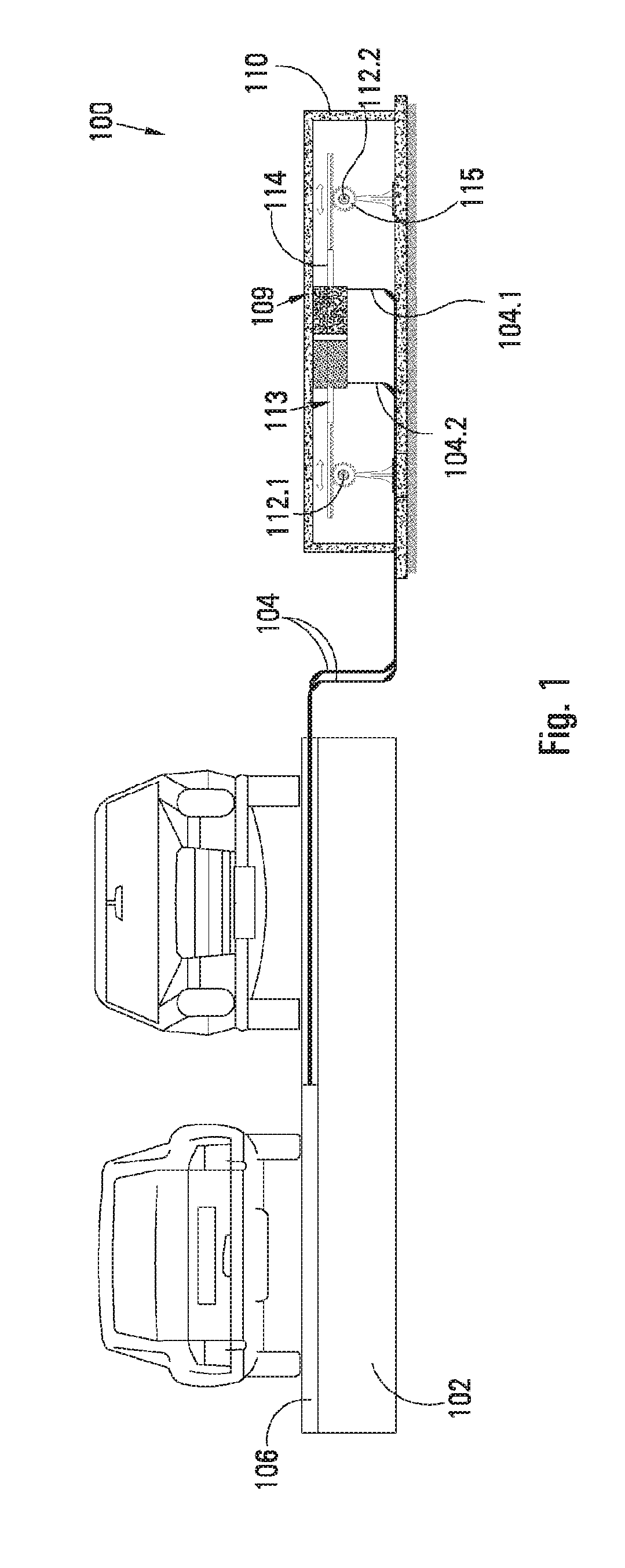
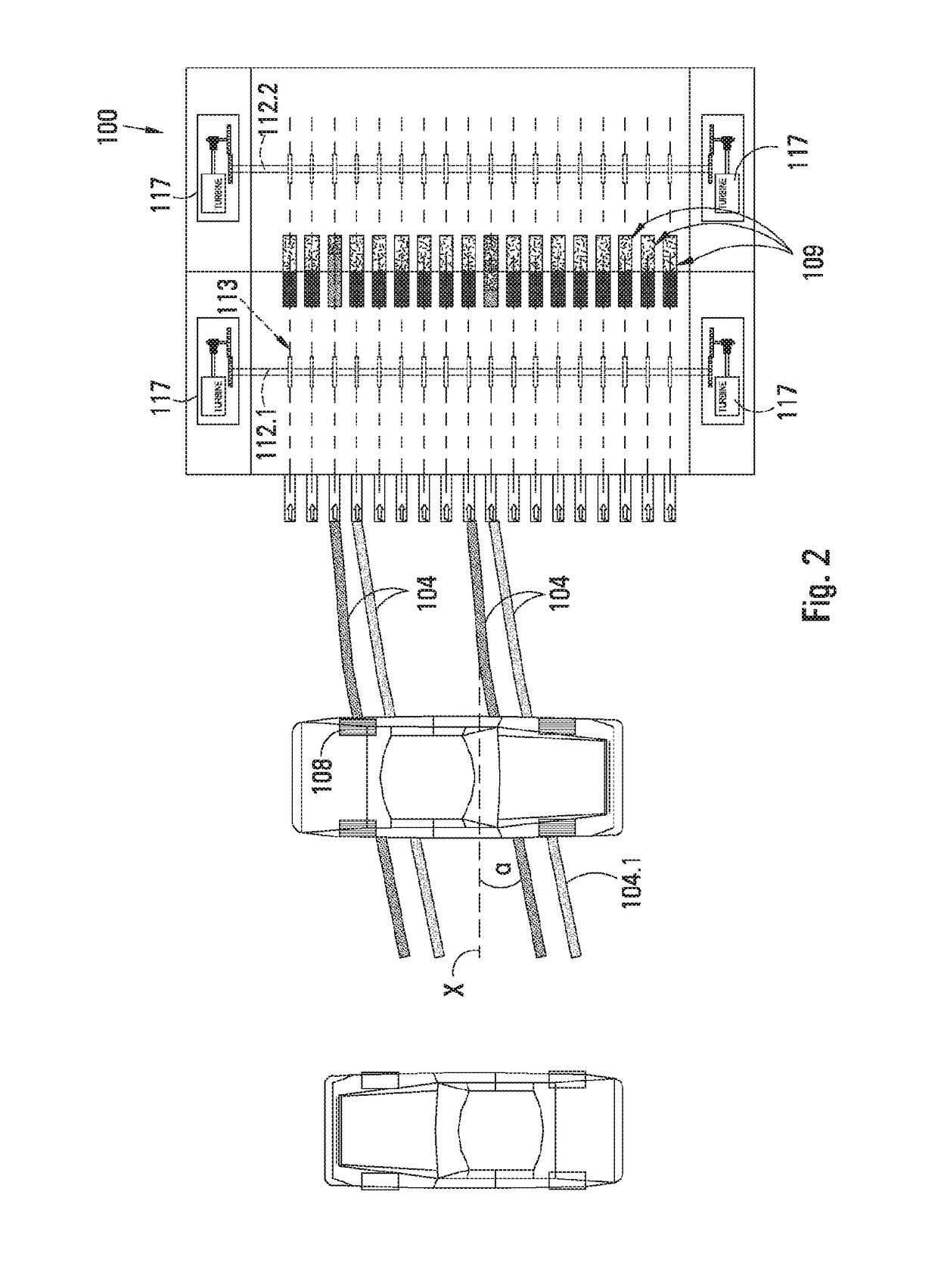
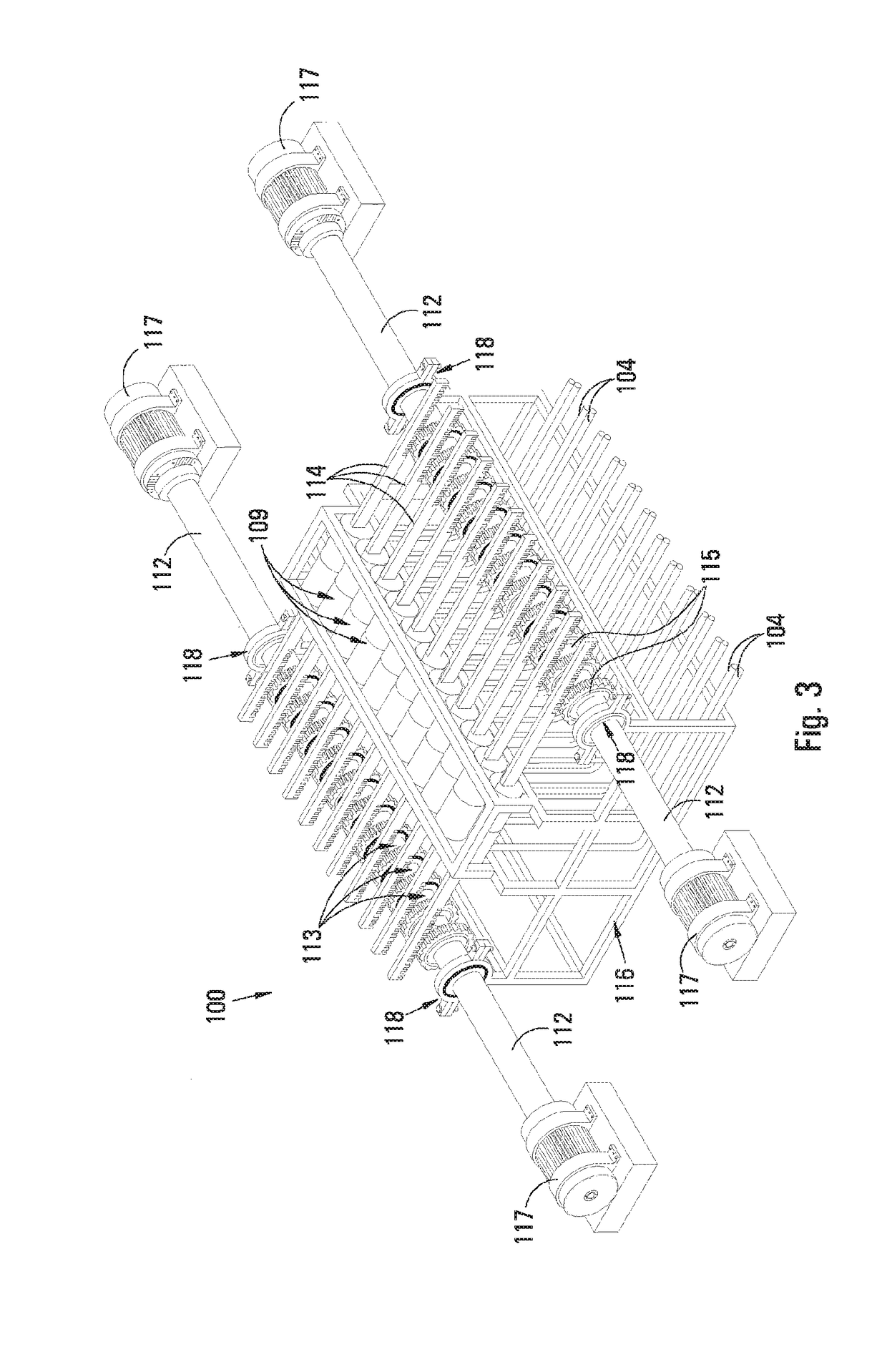
[0035]For general understanding of the present invention, reference is made to the accompanying figures. In the figures, like reference numerals have been used throughout ...


PUM


Abstract

An energy harvesting system (100) for harvesting energy from vehicles travelling on a road (102). The system (100) includes a plurality of flexible hoses (104) which are embedded in a road overlay (106). Each hose (104) holds a hydraulic fluid, e.g. water, such that, when a vehicle wheel (108) passes over the hose (104), the fluid is displaced. The system (100) further comprises a plurality of double-acting hydraulic fluid cylinders (109) which are in fluid flow communication with the fluid in the hoses (104) and are configured to convert pressure applied to the fluid into rotary motion which drives an electrical generator. One hose is connected to each end of the cylinder (109) to drive it in opposite directions to induce linear reciprocating motion which is converted to rotary motion by way of a mechanical drivetrain. Due to the double action, it drives at least two drive shafts simultaneously.

Description

FIELD OF INVENTION[0001]The invention is in the field of power generation, and relates in particular to a system for harvesting energy from vehicles travelling on roads and converting the harvested energy into electrical power.BACKGROUND OF INVENTION[0002]Current renewable energy efforts are based on the use of traditional systems for harvesting energy from solar rays, wind, tidal flow, biomass and recycling of waste products. These systems, although effective in contributing to power in our electricity grids, often do not come without problems. Very often these traditional systems are made from complicated technology and some of them are effective only when certain atmospheric parameters are met or conditions are suitable.[0003]Roads are generally viewed as dead and passive infrastructure. In practice, very little attention has been given to harvesting massive amounts of energy that is transferred by vehicles or automobiles onto or into roads. The Applicant believes that these infr...

Claims


Application Information

Patent Timeline
IPC IPC(8): H02K7/18H02N2/18F01B23/10F16H19/04F16H7/06
CPCH02K7/1861H02K7/1823H02N2/18F01B23/10F16H19/043F16H7/06F03G7/00F03G7/04F03G7/08F03G7/085
Inventor MOKOENENE, RAMOKOTJO CLEMENT
Owner EPITOME PROPERTY INVESTMENTS PTY LTD
Why Eureka
Try Eureka