Fin ray-type wiper comprising a flexible structure optimized for demolding

a flexible structure and wiper technology, applied in the field of windshield wiper devices, can solve the problems of easy loss of contact between the wiper blade and the windshield, and inability to reliably prevent smearing in a simple manner, and achieve the effects of simple and cost-effective, simple injection molding dies, and simple production of wiper blades

Active Publication Date: 2019-09-24
ROBERT BOSCH GMBH
View PDF6 Cites 0 Cited by
  • Summary
  • Abstract
  • Description
  • Claims
  • Application Information

AI Technical Summary

Benefits of technology

[0005]It is the object of the present invention to ensure a reliable and substantially smear-free wiping of a windshield of a vehicle, wherein the production of the wiper blade is simplified.

Problems solved by technology

In particular on windshields having pronounced changes in curvature, the wiper blade easily loses contact with the windshield.
This may result, in particular in the case of windshields having a pronounced curvature, in wiping areas not being wiped or in smearing.
Since a wiping operation has to be optimized for a multiplicity of parameters, such as, for example, the amount of rain falling on the windshield, a possible snow loading occurring on the windshield, the speed of the vehicle and associated wind pressure on the wiper arm, smearing cannot be reliably prevented in a simple manner by adaptation of the pressure of the wiper arm on the windshield.

Method used


Image

  • Fin ray-type wiper comprising a flexible structure optimized for demolding
  • Fin ray-type wiper comprising a flexible structure optimized for demolding
  • Fin ray-type wiper comprising a flexible structure optimized for demolding

Examples


Embodiment Construction

[0027]Unless noted otherwise, the same reference numbers are used below for identical and identically acting elements.

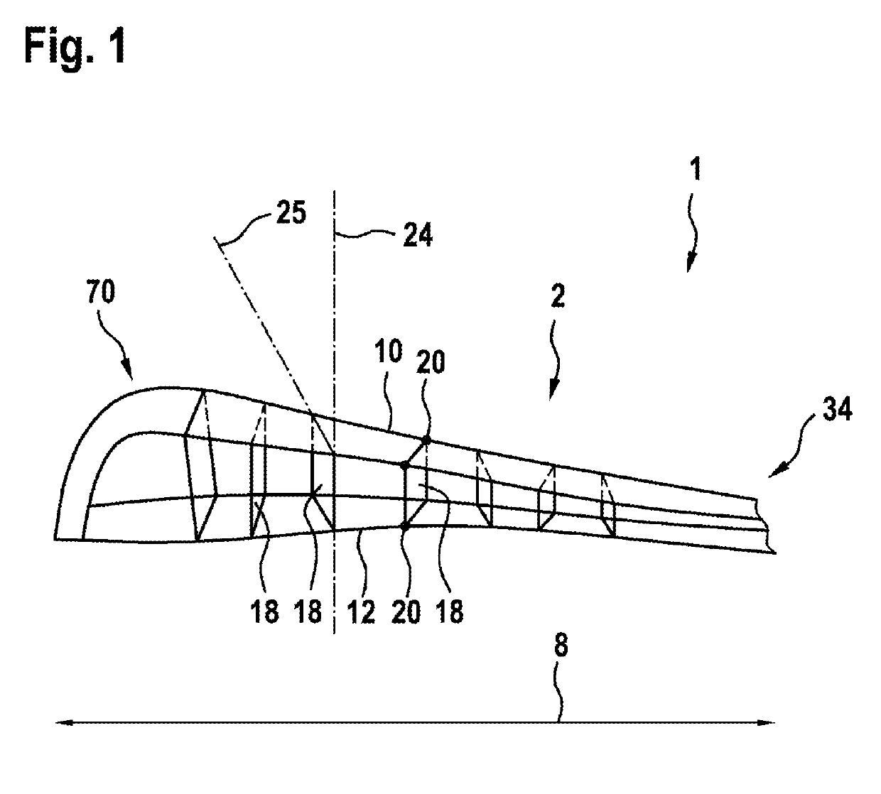
[0028]FIG. 1 shows a perspective illustration of a wiper arm 1 of a windshield wiper device, wherein the wiper arm 1 has a wiper blade head 70 and a wiper blade 2 with an arrangement, optimized for demolding, of connecting elements 18, according to embodiments of the invention. The wiper blade 2 extends here from the wiper blade head 70 to a connecting position 34.

[0029]According to embodiments, the wiper blade 2 has an elongate upper part 10 and an elongate lower part 12, which are configured to be at least partially bendable, wherein the lower part 12 faces a windshield 4 during operation of the windshield wiper device. Furthermore, a plurality of connecting elements 18 for connecting the upper part 10 and the lower part 12 are provided, wherein the connecting elements 18 are spaced apart from one another along a longitudinal extent 8 of the wiper blade and are att...


PUM

PropertyMeasurementUnit
demolding angleaaaaaaaaaa
thicknessaaaaaaaaaa

Abstract

The invention relates to a windshield wiper device for a vehicle, for wiping a window (4), comprising a wiper blade (2) that has an elongate upper part (10) and an elongate lower part (12) which are at least partly flexible. Also provided is a plurality of connecting elements (18) for connecting the upper part (10) and the lower part (12), the connecting elements (18) being spaced apart along a longitudinal direction (8) of the wiper blade (2) and being attached to the upper part (10) and / or the lower part (12) by a rotary joint (20), and the connecting elements (18) being designed to allow a motion of the upper part (10) and the lower part relative to each other with a motion component along the longitudinal direction (8) of the wiper blade (2). Each connecting element (18) extends along a longitudinal axis (24) of the connecting element (18) and along a transverse axis (25) running perpendicular to the longitudinal axis (24), which runs from the upper part (10) to the lower part (12). The transverse axes (25) of at least two connecting elements (18) adjoining each other along the longitudinal direction (8) define a demolding angle (β) of at least 0.5° relative to one another.

Description

BACKGROUND OF THE INVENTION[0001]The invention relates to a windshield wiper device for a vehicle, in particular a motor vehicle, and to a method for producing a wiper blade for a windshield wiper device.[0002]Windshield wiper devices typically have a wiper arm or wiper lever, wherein a wiper blade is moved over the windshield of a motor vehicle. The wiper blade is moved here between a first turning position and a second turning position. For this purpose, the wiper arm is connected via a drive shaft to a wiper motor. In particular on windshields having pronounced changes in curvature, the wiper blade easily loses contact with the windshield. This may result, in particular in the case of windshields having a pronounced curvature, in wiping areas not being wiped or in smearing.[0003]Since a wiping operation has to be optimized for a multiplicity of parameters, such as, for example, the amount of rain falling on the windshield, a possible snow loading occurring on the windshield, the ...

Claims


Application Information

Patent Timeline
Patent Type & Authority Patents(United States)
IPC IPC(8): B60S1/38B29C45/33B60S1/34B29L31/30
CPCB29C45/33B60S1/38B60S1/3801B60S2001/3825B60S2001/3898B60S2001/3812B60S1/3427B29L2031/305
Inventor MERZ, JOCHENNAFZ, HARTMUTWEILER, MICHAEL
Owner ROBERT BOSCH GMBH
Why Eureka
Try Eureka