Fin ray wiper

a technology of a wiper arm and a flange, which is applied in the direction of vehicle maintenance, vehicle cleaning, transportation and packaging, etc., can solve the problems of inability to reliably prevent smearing and easily lose the contact of the wiper blade with the window, and achieve the effect of convenient handling during mounting or dismounting of the wiper arm on or from the drive shaft, simple actuation of the actuation device, and low production cos

Active Publication Date: 2019-04-30
ROBERT BOSCH GMBH
View PDF14 Cites 0 Cited by
  • Summary
  • Abstract
  • Description
  • Claims
  • Application Information

AI Technical Summary

Benefits of technology

[0005]It is the object of the present invention to ensure reliable, substantially smear-free wiping of a window of a vehicle, with a secure attachment of the wiper arm of the window wiper device to a drive shaft of an associated drive unit being provided.
[0019]In yet further embodiments, the actuating device and / or the associated blocking element may be arranged between the wiper blade head and one of the multiple connecting elements. In this way, it is advantageously possible to realize simple actuation of the actuating device and / or of the associated blocking element, whereby the handling during mounting or dismounting of the wiper arm on or from the drive shaft is facilitated.

Problems solved by technology

In particular on windshields with intense changes in curvature, the wiper blade easily loses contact with the window.
Since a wiping process must be optimized with regard to a multiplicity of parameters, such as for example an amount of rain falling on the window, a possible snow load on the window, the speed of the vehicle and associated wind pressure on the wiper arm, smearing cannot be reliably prevented simply by adapting the pressure of the wiper arm on the window.

Method used


Image

  • Fin ray wiper
  • Fin ray wiper
  • Fin ray wiper

Examples


Embodiment Construction

[0031]Below, unless stated otherwise, the same reference designations are used for identical elements and elements of identical action.

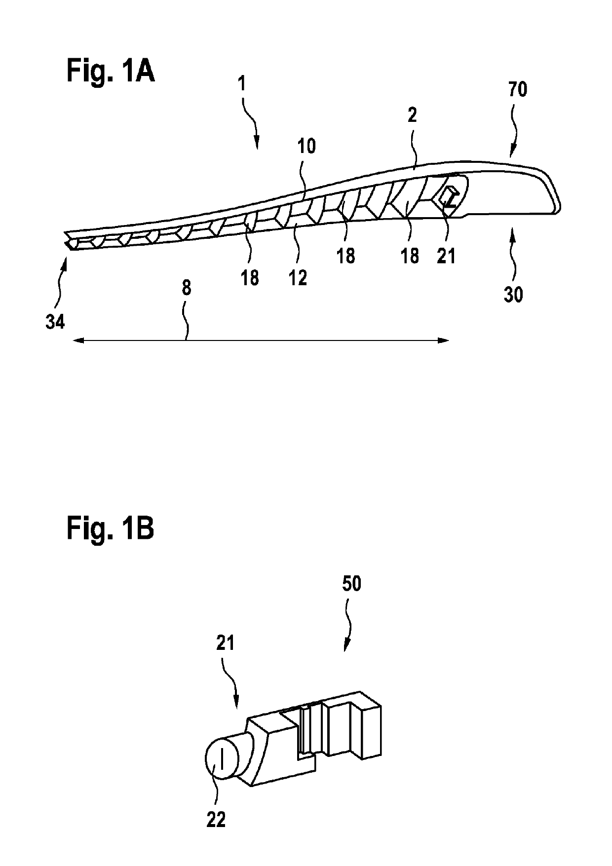
[0032]FIG. 1 is a schematic illustration of a wiper arm 1 of a window wiper device for a vehicle, in particular for a motor vehicle. The perspective illustration of FIG. 1 shows a wiper blade head 70 which can be lifted off a drive shaft of a window wiper drive unit of the vehicle and which is illustrated in a state in which it is engaged into an actuating device 21.

[0033]Such window wiper devices typically have no joint for the lifting of the wiper blade 2 or of a wiper lip from a window, for example a window of a motor vehicle. For example, the wiper blade 2 is released by way of a quick-action fastener (Quickfix) from a fastening element provided on the drive shaft.

[0034]In the wiper blade head 70 there is accommodated a wiper-blade-side fastening part 30 (not visible in FIG. 1A) which is designed for connecting the wiper arm 1 releasably to the d...


PUM


Abstract

The present invention relates to a window-wiping device (100) for a vehicle, comprising a wiper blade (2) having an elongate upper part (10) and an elongate lower part (12), which are designed to be at least partially flexible. Also provided is a plurality of connecting elements (18) for connecting the upper part (10) and the lower part (12), the connecting elements (18) being spaced apart along a longitudinal extent (8) of the wiper blade (2) and being attached to the upper part (10) and / or the lower part (12) by a rotary joint, and the connecting elements (18) being designed to allow a motion of the upper part (10) and the lower part relative to each other with a motion component along the longitudinal extent (8) of the wiper blade (2). The window-wiping device also has a wiper-blade-side fastening part (30), which is accommodated in the wiper blade head (70), and a fastening element (50), which can be attached to the drive shaft (33) and into which the wiper-blade-side fastening part (30) can be locked and which has an actuating device (21), which is designed to release the wiper-blade-side fastening part (30) from the fastening element (50) as a result of an actuation, wherein the actuating device (21) has a blocking element (22), which is designed to block actuation of the actuating device (21).

Description

BACKGROUND OF THE INVENTION[0001]The invention relates to a window wiper device for a vehicle, in particular a motor vehicle.[0002]Window wiper devices typically have a wiper arm or wiper lever, wherein a wiper blade is moved on the window of a motor vehicle. Here, the wiper blade is moved between a first reversal point and a second reversal point. For this purpose, the wiper arm is connected by way of a drive shaft to a wiper motor. In particular on windshields with intense changes in curvature, the wiper blade easily loses contact with the window. This can give rise, in particular in the case of intensely curved windows, to non-wiped wiping areas, and / or to smearing.[0003]Since a wiping process must be optimized with regard to a multiplicity of parameters, such as for example an amount of rain falling on the window, a possible snow load on the window, the speed of the vehicle and associated wind pressure on the wiper arm, smearing cannot be reliably prevented simply by adapting th...

Claims


Application Information

Patent Timeline
Patent Type & Authority Patents(United States)
IPC IPC(8): B60S1/34B60S1/38
CPCB60S1/3801B60S1/345B60S1/3427B60S1/3452B60S1/3459B60S1/3495B60S1/3436B60S2001/3812
Inventor HAUSER, FLORIANWEILER, MICHAELHACKL, VIKTORERNST, WALDEMAR
Owner ROBERT BOSCH GMBH
Why Eureka
Try Eureka