AI technical title is built by Patsnap AI team. It summarizes the technical point description of the patent document.
a technology of led packages and reflectivity layers, applied in semiconductor devices, semiconductor/solid-state device details, electrical devices, etc., can solve problems such as the reduction of package emission efficiency, and achieve the effect of reducing the emission efficiency of packages and reducing the emission efficiency
Active Publication Date: 2019-09-24
CREELED INC
View PDF127 Cites 0 Cited by
Summary
Abstract
Description
Claims
Application Information
AI Technical Summary
This helps you quickly interpret patents by identifying the three key elements:
Problems solved by technology
Method used
Benefits of technology
Benefits of technology
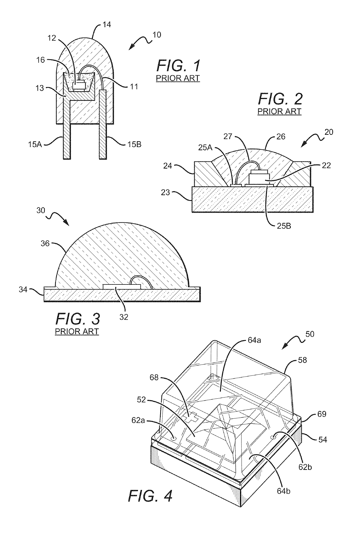
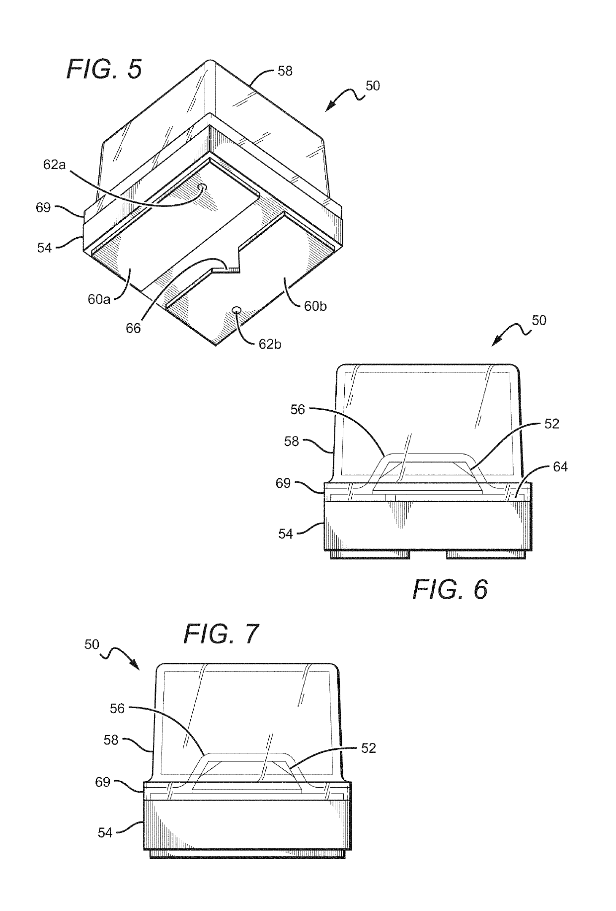
[0012]The present invention is generally directed to emitter or LED packages that are compact and efficiently emit light, and can comprise encapsulants with planar surfaces that refract and / or reflect light within the package encapsulant. In some embodiments, the packages can also comprise a submount with one LED, while other embodiments can comprise a plurality of LEDs. In the single LED embodiments, a blanket conversion material layer can cover the LED, and in multiple LED embodiments the blanket conversion material layer can be on one or more of the LEDs. The blanket conversion material may also cover at least part of the submount. The encapsulant can be on the submount, over the LEDs, and over at least part of the blanket conversion material. Some of the light reflected within the encapsulant, due, for example, to total internal reflection from planar or otherwise shaped encapsulant surface, will reach the conversion material, where it may be scattered or absorbed and converted and then emitted omnidirectionally. This allows for reflected light to now escape from the encapsulant. This allows for efficient emission and a broader emission profile, for example when compared to conventional packages with hemispheric encapsulants or lenses.
[0013]In embodiments, the LED packages can be provided reflective layers to enhance light package light extraction. The reflective layers can be arranged to reflect light that otherwise might encounter light absorbing surfaces. These surfaces can absorb some or all of the light, which can lead to a reduction in package emission efficiency.
Problems solved by technology
These surfaces can absorb some or all of the light, which can lead to a reduction in package emission efficiency.
Method used
Image
Click on the blue label to locate the original text in one second.
Reading with bidirectional positioning of images and text.
Examples
Embodiment Construction
[0183]The present invention is directed to different embodiments of LED package structures having a light source that comprises a single or plurality of LED chips. The LED packages can be arranged in different ways and are relatively small, while at the same time are efficient, reliable and cost effective. Some embodiments according to the present invention can emit with same or similar efficiency compared to similar LED packages with fully hemispheric encapsulants, but can be smaller and less expensive to manufacture.
[0184]The packages according to the present invention can provide these improvements by having conversion material and encapsulants that are arranged and shaped to capitalize on the total internal reflection (TIR) of light within the package. That is, the encapsulant can be shaped such that light incident on the package encapsulant at angles greater than the critical angle for TIR can be reflected back towards a conversion material within the package such that the ligh...
PUM
Abstract
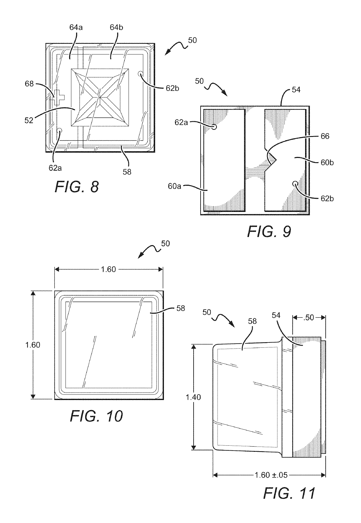
LED packages are disclosed that are compact and efficiently emit light, and can comprise encapsulants with curved and planar surfaces. The packages can comprise a submount with a one or a plurality of LEDs, and in those with a plurality of LEDs each of the LEDs can emit the same or different wavelengths of light than the others. A blanket conversion material layer can be included on at least some of the LEDs and the submount. The encapsulant can be on the submount, over at least some of the LEDs, with each of the planar surfaces being vertical and aligned with one of the edges of the submount. The packages can also comprise reflective layers to minimize losses due to light absorption, which in turn can increase the overall package emission efficiency.
Description
[0001]This application is a continuation in part of and claims the benefit of U.S. patent application Ser. No. 13 / 957,290, filed on Aug. 1, 2013, which is a continuation-in-part of U.S. patent application Ser. No. 13 / 770,389, filed on Feb. 19, 2013, which is a continuation-in-part of and claims the benefit of U.S. patent application Ser. No. 13 / 649,067, and U.S. patent application Ser. No. 13 / 649,052, both of which were filed on Oct. 10, 2012, and both of which claim the benefit of U.S. Provisional Patent Application Ser. No. 61 / 658,271, filed on Jun. 11, 2012, U.S. Provisional Patent Application Ser. No. 61 / 660,231, filed on Jun. 15, 2012, and U.S. Provisional Patent Application Ser. No. 61 / 696,205, filed on Sep. 2, 2012. Each of the applications cited in this paragraph are incorporated by reference as if fully set forth herein.BACKGROUND OF THE INVENTION[0002]Field of the Invention[0003]This invention pertains to solid state light emitters and in particular to compact light emitti...
Claims
Application Information
Patent Timeline
Application Date:The date an application was filed.
Publication Date:The date a patent or application was officially published.
First Publication Date:The earliest publication date of a patent with the same application number.
Issue Date:Publication date of the patent grant document.
PCT Entry Date:The Entry date of PCT National Phase.
Estimated Expiry Date:The statutory expiry date of a patent right according to the Patent Law, and it is the longest term of protection that the patent right can achieve without the termination of the patent right due to other reasons(Term extension factor has been taken into account ).
Invalid Date:Actual expiry date is based on effective date or publication date of legal transaction data of invalid patent.

