LED package with encapsulant having curved and planar surfaces

a technology of encapsulant and encapsulant, which is applied in the direction of basic electric elements, electrical equipment, and semiconductor devices, can solve the problems of high inefficiency of light sources, chronic and acute poisoning, and loss of as much as 95% of input energy, and achieve the effect of a broader emission profile and efficient light emission

Active Publication Date: 2018-02-06
CREELED INC
View PDF107 Cites 42 Cited by
  • Summary
  • Abstract
  • Description
  • Claims
  • Application Information

AI Technical Summary

Benefits of technology

[0012]The present invention is generally directed to emitter or LED packages that are compact and efficiently emit light, and can comprise encapsulants with planar surfaces that refract and / or reflect light within the package encapsulant. In some embodiments, the packages can also comprise a submount with one LED, while other embodiments can comprise a plurality of LEDs. In the single LED embodiments, a blanket conversion material layer can cover the LED, and in multiple LED embodiments the blanket conversion material layer can be on one or more of the LEDs. The blanket conversion material may also cover at least part of the submount. The encapsulant can be on the submount, over the LEDs, and over at least part of the blanket conversion material. Some of the light reflected within the encapsulant, due, for example, to total internal reflection from planar or otherwise shaped encapsulant surface, will reach the conversion material, where it may be scattered or absorbed and converted and then emitted omnidirectionally. This allows for reflected light to now escape from the encapsulant. This allows for efficient emission and a broader emission profile, for example when compared to conventional packages with hemispheric encapsulants or lenses.
[0013]In other embodiments, the LED packages can be provided with hybrid encapsulants that can result in an LED packages with differing emission profiles, with the hybrid encapsulants having surfaces that are not planar. Some of these embodiments can comprise an encapsulant with one or more planar and curved surfaces, with the resulting package providing or more focused or narrow emission profile useful in certain applications. The different embodiments can provide unique dimensional relationships which can include: curved surface to radius of curvature to submount size, encapsulant height, width and distance to the edge of the LED chip(s), distance between LED chips in a multiple chip embodiment, LED epitaxial area verses package area, emission pattern per package footprint, more light output power per package footprint, improved mixing or blending or uniformity of different colors emitted by the package. The different emitter and LED packages according to the present invention can use different light sources with different sizes, shapes and features.

Problems solved by technology

However, such lamps are highly inefficient light sources, with as much as 95% of the input energy lost, primarily in the form of heat or infrared energy.
One common alternative to incandescent lamps, so-called compact fluorescent lamps (CFLs), are more effective at converting electricity into light but require the use of toxic materials which, along with its various compounds, can cause both chronic and acute poisoning and can lead to environmental pollution.
While the reflective cup 13 may direct light in an upward direction, optical losses may occur when the light is reflected (i.e. some light may be absorbed by the reflective cup due to the less than 100% reflectivity of practical reflector surfaces).
In addition, heat retention may be an issue for a package such as the package 10 shown in FIG. 1, since it may be difficult to extract heat through the leads 15A, 15B.
Further, these devices generally produce a Lambertian emission pattern that is not always ideal for wide emission area applications.

Method used


Image

  • LED package with encapsulant having curved and planar surfaces
  • LED package with encapsulant having curved and planar surfaces
  • LED package with encapsulant having curved and planar surfaces

Examples


Embodiment Construction

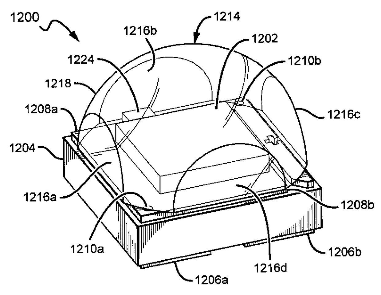
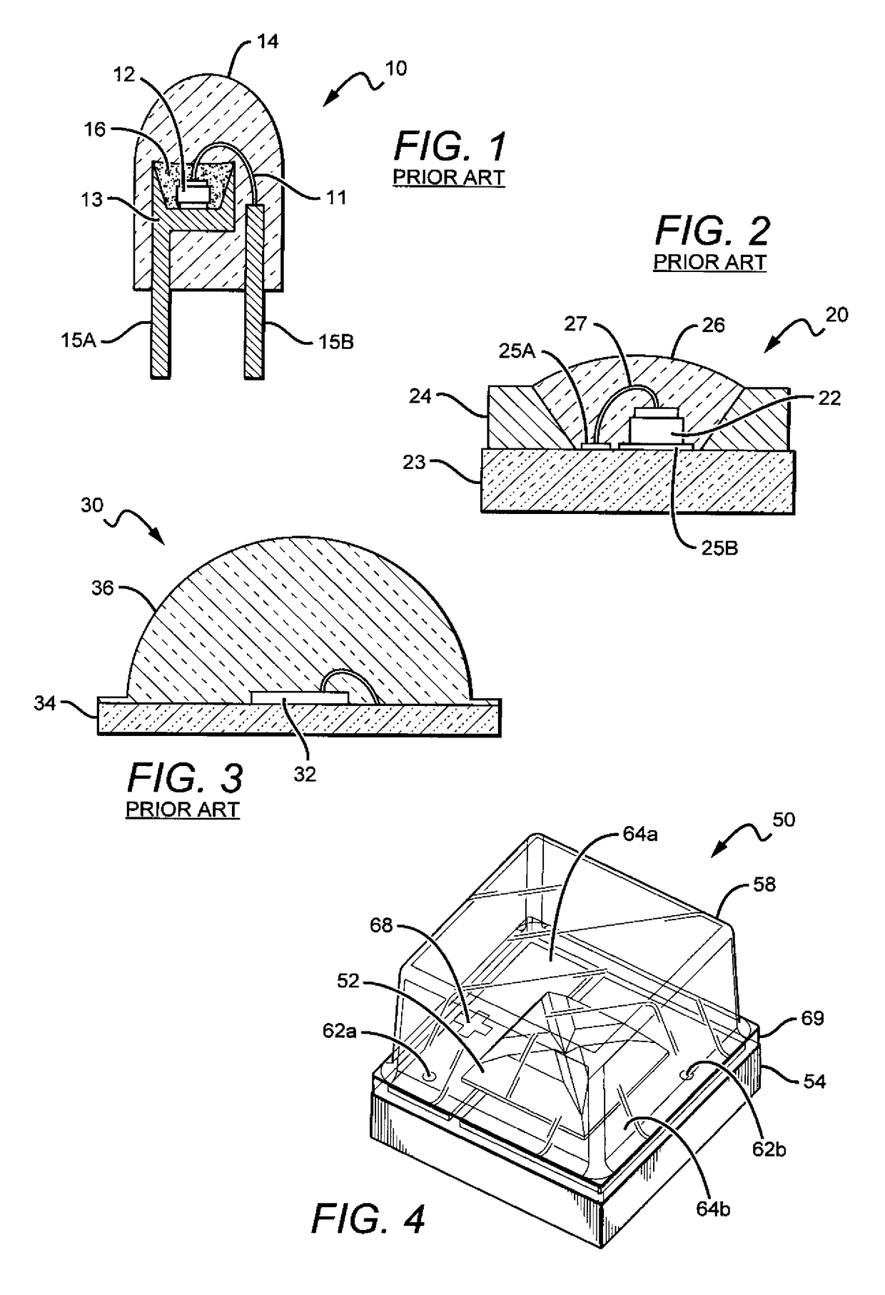
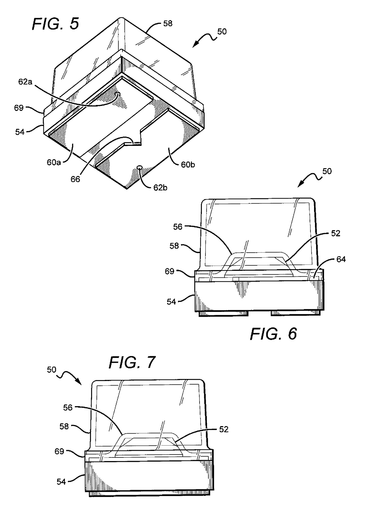
[0155]The present invention is directed to different embodiments of LED package structures having a light source that comprises a single or plurality of LED chips. The LED packages can be arranged in different ways and are relatively small, while at the same time are efficient, reliable and cost effective. Some embodiments according to the present invention can emit with same or similar efficiency compared to similar LED packages with fully hemispheric encapsulants, but can be smaller and less expensive to manufacture.

[0156]The packages according to the present invention can provide these improvements by having conversion material and encapsulants that are arranged and shaped to capitalize on the total internal reflection (TIR) of light within the package. That is, the encapsulant can be shaped such that light incident on the package encapsulant at angles greater than the critical angle for TIR can be reflected back towards a conversion material within the package such that the ligh...


PUM


Abstract

LED packages are disclosed that are compact and efficiently emit light, and can comprise encapsulants with curved and planar surfaces. The packages can comprise a submount with a one or a plurality of LEDs, and in those with a plurality of LEDs each of the LEDs can emit the same or different wavelengths of light than the others. A blanket conversion material layer can be included on at least some of the LEDs and the submount. The encapsulant can be on the submount, over at least some of the LEDs, with each of the planar surfaces being vertical and aligned with one of the edges of the submount. The encapsulant can also have a upper curved surface with a relatively large radius of curvature, with the combination of curved and planar surfaces resulting in efficient emission of light with a relatively narrow emission profile.

Description

[0001]This application is a continuation-in-part of U.S. patent application Ser. No. 13 / 770,389, filed on Feb. 19, 2013, which is a continuation-in-part of and claims the benefit of U.S. patent application Ser. No. 13 / 649,067, and U.S. patent application Ser. No. 13 / 649,052, both of which were filed on Oct. 10, 2012, and both of which claim the benefit of U.S. Provisional Patent Application Ser. No. 61 / 658,271, filed on Jun. 11, 2012, U.S. Provisional Patent Application Ser. No. 61 / 660,231, filed on Jun. 15, 2012, and U.S. Provisional Patent Application Ser. No. 61 / 696,205, filed on Sep. 2, 2012. Each of the applications cited in this paragraph are incorporated by reference as if fully set forth herein.BACKGROUND OF THE INVENTION[0002]Field of the Invention[0003]This invention pertains to solid state light emitters and in particular to light emitting diode (LED) packages with one or more LEDs and a hybrid encapsulant comprising planar and curved surfaces.[0004]Description of the Rel...

Claims


Application Information

Patent Timeline
Patent Type & Authority Patents(United States)
IPC IPC(8): H01L33/00H01L33/50H01L33/58H01L33/54H01L25/075H01L33/48
CPCH01L33/505H01L33/508H01L33/54H01L33/58H01L25/0753H01L2224/48247H01L33/486H01L2224/48091H01L2924/00014
Inventor REIHERZER, JESSESIGNOR, ANDREWCLARK, JOSEPH GATESBERGMANN, MICHAEL JOHN
Owner CREELED INC
Why Eureka
Try Eureka