
Surgical instrument with detection sensors

a technology of detection sensors and surgical instruments, applied in the field of surgical instruments, can solve the problems of impede the surgeon's ability to properly identify all the materials or structures present at the surgical site, and it is difficult to visually inspect the differences between healthy and diseased tissu

Active Publication Date: 2019-10-01
CILAG GMBH INT
View PDF6993 Cites 680 Cited by
  • Summary
  • Abstract
  • Description
  • Claims
  • Application Information

AI Technical Summary

Benefits of technology

The patent describes a surgical instrument with a sensor at the end of a shaft that can transmit and receive signals to and from patient tissue at a surgical site. The sensor can be a laser sensor or a near infrared spectrometer sensor. The sensor data can be used to determine the physical and chemical composition of the patient tissue, and a display can show the data in a graphical form. The instrument can also have a processor to access and analyze the sensor data. The technical effect of this invention is to provide a surgical instrument with a sensor that can provide valuable information about patient tissue at the surgical site, allowing for better surgical procedures and outcomes.

Problems solved by technology

However, there are few other indicators for a surgeon to be able to distinguish the types of tissues present.
In addition, artificial implants, substances underneath tissue that are unseen, and other modifications made to the body of the patient, either through previous surgeries or by ingestion of substances, for example, may impede a surgeon's ability to properly identify all of the materials or structures present at a surgical site.
Moreover, it may be difficult to visually inspect differences between healthy and diseased tissue, in some cases.

Method used


Image

  • Surgical instrument with detection sensors
  • Surgical instrument with detection sensors
  • Surgical instrument with detection sensors

Examples


Embodiment Construction

[0139]Applicant of the present application owns the following patent applications that were filed on Apr. 15, 2016, and which are each herein incorporated by reference in their respective entireties:

[0140]U.S. patent application Ser. No. 15 / 130,575, entitled STAPLE FORMATION DETECTION MECHANISMS, now U.S. Patent Application Publication No. 2017 / 0296189;

[0141]U.S. patent application Ser. No. 15 / 130,588, entitled SURGICAL INSTRUMENT WITH IMPROVED STOP / START CONTROL DURING A FIRING MOTION, now U.S. Patent Application Publication No. 2017 / 0296179;

[0142]U.S. patent application Ser. No. 15 / 130,595, entitled SURGICAL INSTRUMENT WITH ADJUSTABLE STOP / START CONTROL DURING A FIRING MOTION, now U.S. Patent Application Publication No. 2017 / 0296180;

[0143]U.S. patent application Ser. No. 15 / 130,566, entitled SURGICAL INSTRUMENT WITH MULTIPLE PROGRAM RESPONSES DURING A FIRING MOTION, now U.S. Patent Application Publication No. 2017 / 0296177;

[0144]U.S. patent application Ser. No. 15 / 130,571, entitled...


PUM


Abstract

Aspects of the present disclosure are presented for a surgical instrument having one or more sensors at or a near an end effector and configured to aide in the detection of tissues and other materials and structures at a surgical site. The detections may then be used to aide in the placement of the end effector and to confirm which objects to operate on, or alternatively, to avoid. Examples of sensors include laser sensors used to employ Doppler shift principles to detect movement of objects at the surgical site, such as blood cells; resistance sensors to detect the presence of metal; monochromatic light sources that allow for different levels of absorption from different types of substances present at the surgical site, and near infrared spectrometers with small form factors.

Description

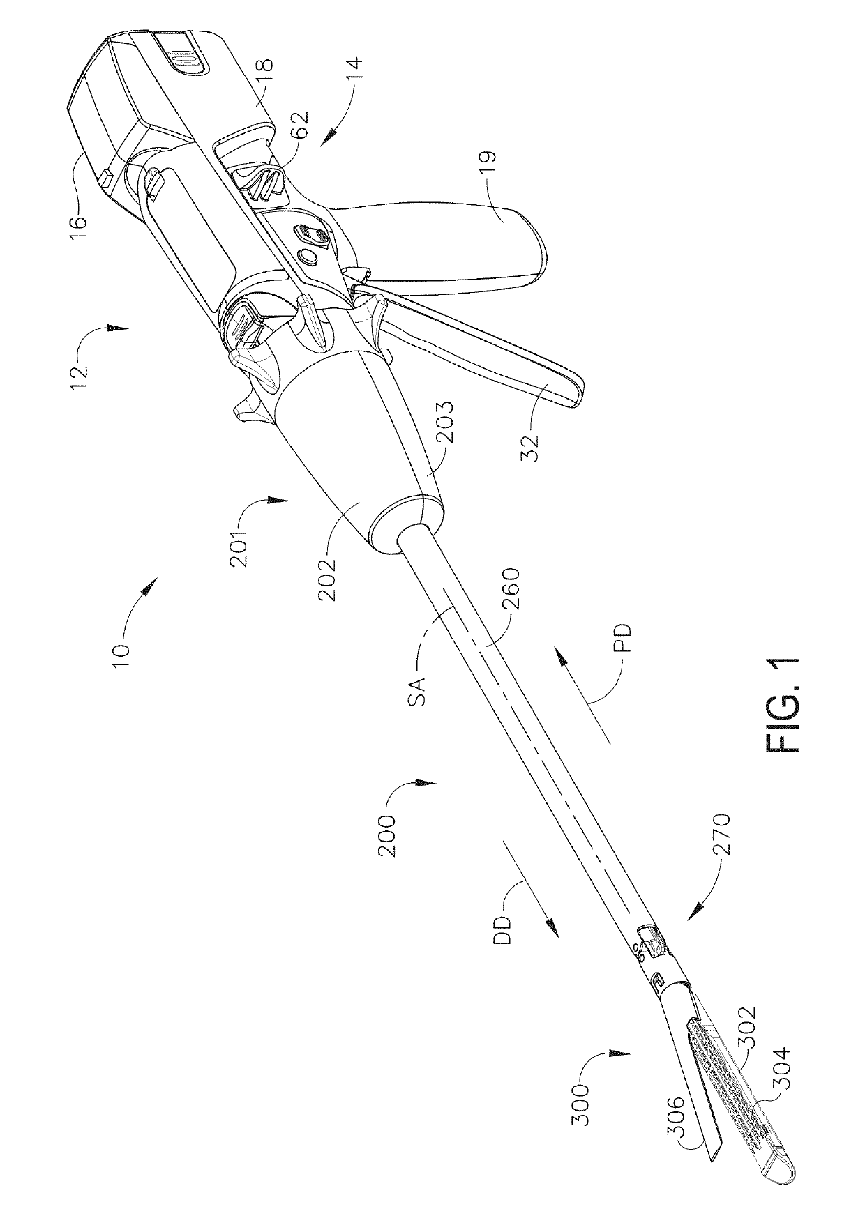
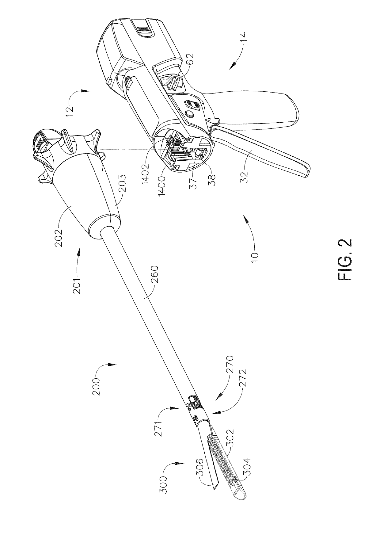
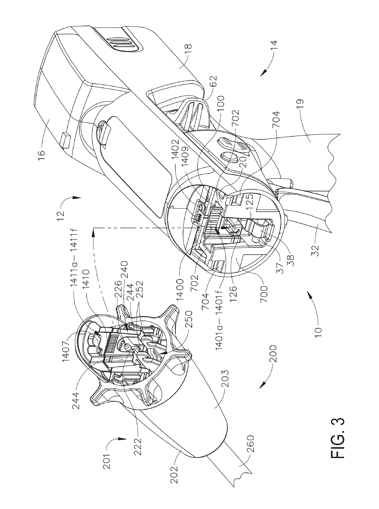
TECHNICAL FIELD[0001]The present disclosure relates to surgical instruments and, in various circumstances, to surgical stapling and cutting instruments and staple cartridges therefor that are designed to staple and cut tissue. More particularly, the present disclosure is related generally to medical devices with various sensors configured to aide in surgical procedures. In particular, the present disclosure is related to medical devices with one or more sensors for detecting structures, tissues, and varying materials or substances at or near a surgical site.BACKGROUND[0002]During surgery, a surgeon will have sufficient training and experience to visually identify the various physiological organs and other materials present at a surgical site. Accurately identifying the various organs or other materials is obviously vital to ensuring that a proper surgery is performed. This identification may be determined based on previous experience and training of what specific organs and tissues ...

Claims


Application Information

Patent Timeline
Patent Type & Authority Patents(United States)
IPC IPC(8): A61B17/068A61B5/05A61B5/026A61B5/00A61B5/053A61B17/072A61B90/30A61B90/00A61B17/00A61B17/29A61B5/02
CPCA61B5/053A61B5/0053A61B5/05A61B5/4869A61B17/0686A61B5/0059A61B5/0261A61B17/07207A61B5/7203A61B2562/0223A61B2562/0233A61B2562/0247A61B2562/0219A61B2017/00039A61B2090/0807A61B2017/00061A61B2017/00022A61B2017/0046A61B2017/2927A61B2090/0803A61B2562/0261A61B2017/00066A61B5/02007A61B2017/00398A61B2017/00119A61B2017/07257A61B2017/00026A61B2017/07285A61B2017/00123A61B2017/00199A61B2017/00132A61B2090/309A61B2090/304A61B2017/07271A61B2017/00075A61B2017/00115A61B2017/00725A61B2090/061A61B2090/064A61B2090/065A61B2017/00017A61B2017/00057A61B2017/00734A61B2090/0811A61B2090/0808
Inventor MILLER, CHRISTOPHER C.CUMMINGS, JOHN F.YATES, DAVID C.SHELTON, IV, FREDERICK E.HARRIS, JASON L.
Owner CILAG GMBH INT
Learn More