Hood lifting assembly

a technology for hoods and assemblies, applied in the direction of wing accessories, washers, pedestrian/occupant safety arrangements, etc., can solve the problems of adding cost and manufacturing time to the hood lifting assembly, and complex current resetting mechanisms

a technology for hoods and assemblies, applied in the direction of wing accessories, washers, pedestrian/occupant safety arrangements, etc., can solve the problems of adding cost and manufacturing time to the hood lifting assembly, and complex current resetting mechanisms

US10434974B2Active Publication Date: 2019-10-08JOYSON SAFETY SYST ACQUISITION LLC

Image

  • Hood lifting assembly
  • Hood lifting assembly
  • Hood lifting assembly

Examples


Embodiment Construction

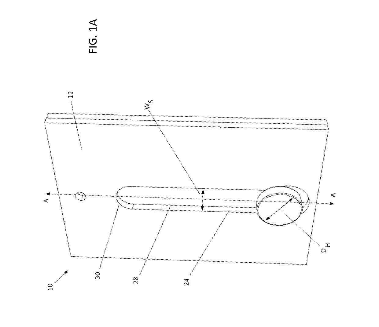
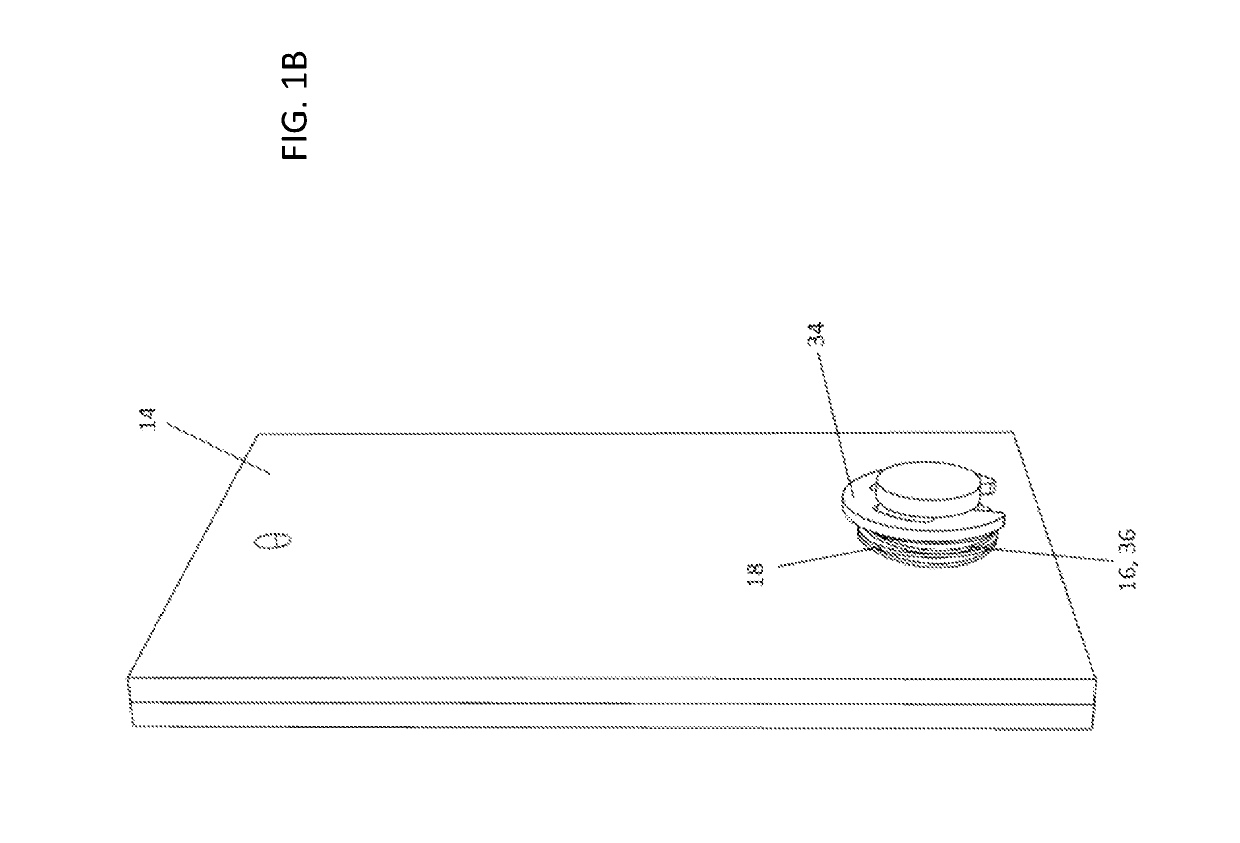
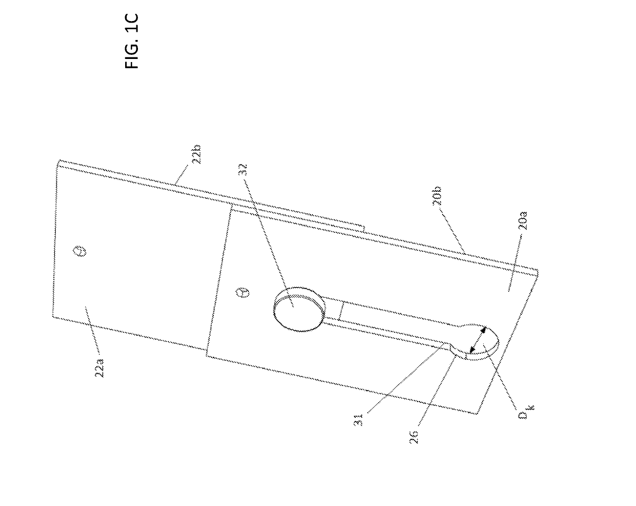
[0032]A hood lifting assembly according to various implementations includes two plates that are slidably coupled together by at least one pin. One plate defines a keyhole slot, and the pin extends through the other plate and through the keyhole slot to slidably couple the plates together. In an initial position of the plates, a head of the pin in spaced apart from a keyhole opening of the keyhole slot, allowing the plates to be moved relative to each other. However, in a reset position, the head of the pin engages, or seats, within the keyhole opening, preventing sliding movement of the plates relative to each other. A hood latch assembly coupled to the movable plate is thus movable from the initial position to a deployed position in which the hood is in a raised position above a vehicle frame and from the deployed position to the reset position in which the hood is securely held in a lowered position.

[0033]In addition, various implementations of a hood lifting assembly include an e...


PUM


Abstract

A hood lifting assembly according to various implementations includes a re-latching feature that allows two slidably coupled plates to be reset, or locked, relative to each other by moving a head of a pin into a keyhole opening of a keyhole slot defined in one of the plates. In an initial position, the head of the pin is spaced apart from the keyhole opening, allowing the pin to move along the keyhole slot from the initial position to a deployed position and then to a reset position. In other implementations, a hood lifting assembly includes an energy absorbing feature. One exemplary energy absorbing feature includes a plate defining an elongated slot that has a narrowed width portion through which a pin travels during movement from the initial position to the deployed position.

Description

CROSS-REFERENCE TO RELATED APPLICATION[0001]This application claims the benefit of U.S. Provisional Application No. 62 / 398,275, entitled “Hood Lifting Assembly,” filed Sep. 22, 2016, the disclosure of which is incorporated herein by reference in its entirety.BACKGROUND[0002]To reduce injuries to a pedestrian that has been hit with a vehicle, some vehicles include a front hood lifting assembly to lift the front of the hood away from the frame of the vehicle. The hood lifting assembly typically includes two slidable plates and a hood lifting actuator that pushes one of the plates upward relative to the other plate. The moveable plate is coupled to a portion of the hood latch assembly and transfers the motion of the hood lifting actuator to the hood latch assembly, causing the front of the hood to be moved upwardly. However, it may be necessary to reset the plates in a lowered position for further operation of the vehicle to ensure the hood does not open when the vehicle is driven or t...

Claims


Application Information

Patent Timeline
08 Oct 2019
Publication
US10434974B2
IPC
B60R21/38; E05B77/08; F16B21/09; F16B43/00; E05F15/50; F16B1/02; E05B17/00; E05B81/10
CPC
B60R21/38; F16B21/09; E05B77/08; E05B81/10; E05Y2900/536; F16B43/003; E05B17/0062; E05F15/50
Inventors
HENCK, JEREMY; WILMOT, LARRY