Roof airbag for vehicle

a technology for roof airbags and vehicles, which is applied in the direction of vehicle components, pedestrian/occupant safety arrangements, vehicular safety arrangments, etc., can solve the problems of occupants ricocheting off the vehicle internally, increasing the damage to occupants, etc., and achieves the goal of maximizing the protection performance of the rab and improving the deployment speed of the airbag cushion

Active Publication Date: 2019-10-22
HYUNDAI MOTOR CO LTD +2
View PDF14 Cites 18 Cited by
  • Summary
  • Abstract
  • Description
  • Claims
  • Application Information

AI Technical Summary

Benefits of technology

[0007]Various aspects of the present invention are directed to providing a roof airbag (RAB) for a vehicle, which is configured for improving a deployment speed of an airbag cushion to maximize protection performance of the RAB by forming the airbag cushion, which covers a sunroof frame, to be separated into a plurality of chambers around a reinforcement member which is formed at the sunroof frame.
[0020]A nut may be engaged with each of both the end portions of the guide bar, preventing the plurality of guide holders from escaping from the guide bar.
[0021]In accordance with the RAB for a vehicle, which is configured with the structure as described above, the deployment speed of the airbag cushion may be prevented from being impeded by the reinforcement member which is formed at the sunroof frame wherein the airbag may be rapidly deployed to improve protection performance for occupants.

Problems solved by technology

When a roof of the vehicle has a panoramic structure, the roof is more easily damaged than a vehicle which omits the panoramic roof structure, and thus injury to an occupant may increase or the occupant internally ricochets off the vehicle due to damage of the roof.

Method used


Image

  • Roof airbag for vehicle
  • Roof airbag for vehicle
  • Roof airbag for vehicle

Examples


Embodiment Construction

[0032]Reference will now be made in detail to various embodiments of the present invention(s), examples of which are illustrated in the accompanying drawings and described below. While the invention(s) will be described in conjunction with exemplary embodiments, it will be understood that the present description is not intended to limit the invention(s) to those exemplary embodiments. On the contrary, the invention(s) is / are intended to cover not only the exemplary embodiments, but also various alternatives, modifications, equivalents, and other embodiments, which may be included within the spirit and scope of the invention as defined by the appended claims.

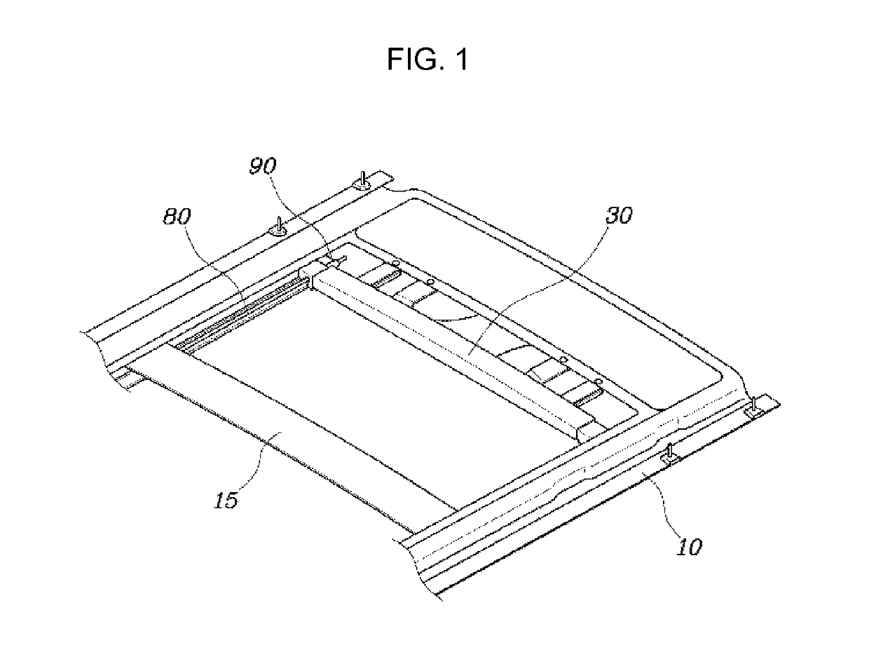
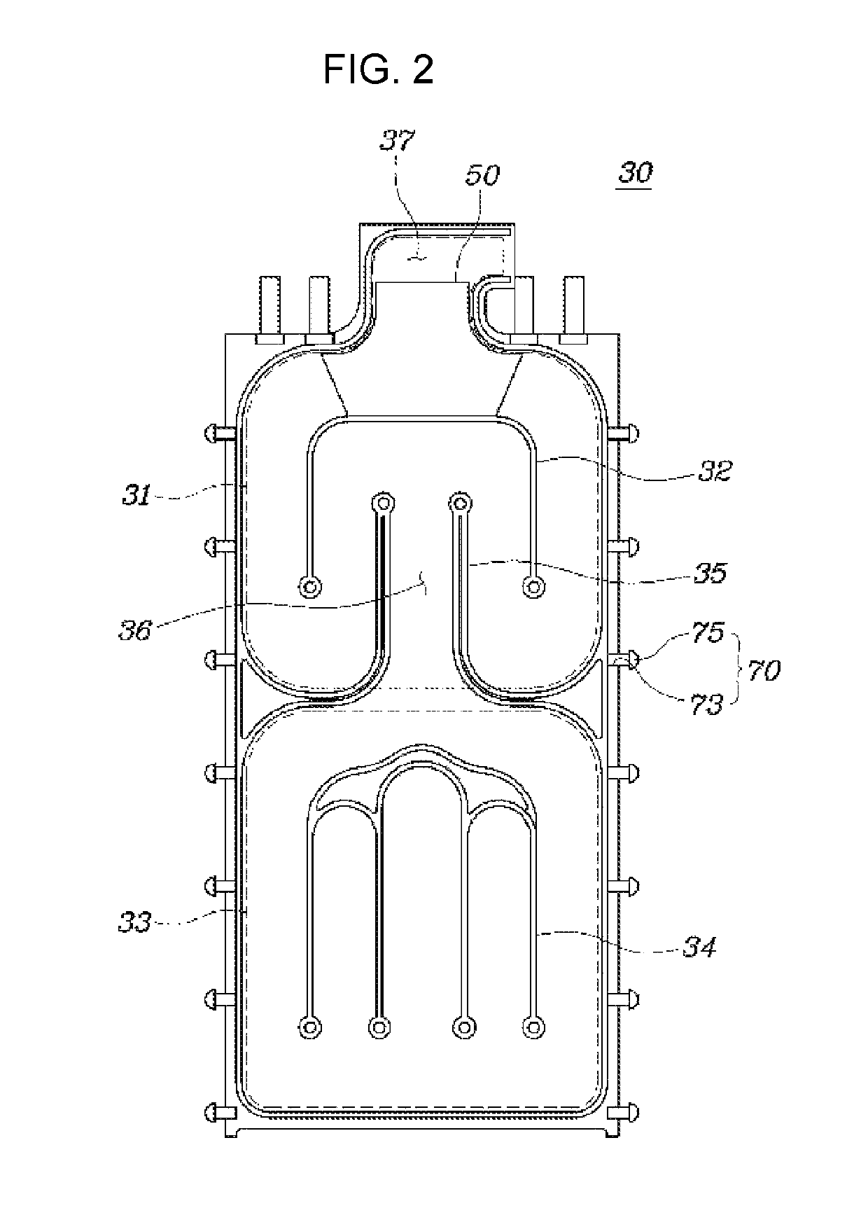
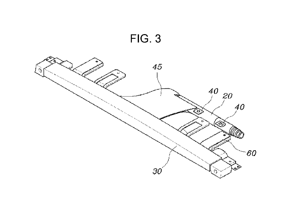
[0033]FIG. 1 is a perspective view illustrating an RAB for a vehicle according to an exemplary embodiment of the present invention, FIG. 2 is a detailed diagram illustrating a shape of an airbag cushion according to an exemplary embodiment of the present invention, and FIG. 3 is a detailed perspective view illustrating a connecti...


PUM


Abstract

A roof airbag for a vehicle may include an inflator at a first end portion of a front and a rear end portions of a sunroof frame configured to discharge deployment gas when activated; a reinforcement member connecting a first and a second side of the sunroof frame at a position between the front and the rear end portions of the sunroof frame; and an airbag cushion at the first end portion of the front and the rear end portions of the sunroof frame in a folded state, and configured with a first chamber configured to cover from the first end portion of the front and the rear end portions of the sunroof frame to a position before reaching the reinforcement member and a second chamber configured to cover from the reinforcement member to the second end portion of the front and the rear end portions of the sunroof frame.

Description

CROSS-REFERENCE(S) TO RELATED APPLICATIONS[0001]The present application claims priority to Korean Patent Application No. 10-2017-0088547, filed on Jul. 12, 2017, the entire contents of which is incorporated herein for all purposes by this reference.BACKGROUND OF THE INVENTIONField of the Invention[0002]The present invention relates to a roof airbag for a vehicle, and, more particularly, to a roof airbag for a vehicle which is configured and formed to smoothly deploy an airbag cushion along a sunroof frame of the vehicle.Description of Related Art[0003]An airbag for a vehicle is a safety device which is configured to deploy an airbag cushion to alleviate an impact which is applied to occupants when a collision occurs, and the airbag for the vehicle includes a driver airbag (DAB), a passenger airbag (PAB), a side airbag (SAB), a curtain airbag (CAB), a knee airbag (KAB), a roof airbag (RAB), and the like.[0004]When a roof of the vehicle has a panoramic structure, the roof is more easi...

Claims


Application Information

Patent Timeline
Patent Type & Authority Patents(United States)
IPC IPC(8): B60R21/233B60R21/214B60R21/262B60R21/231B60R21/261
CPCB60R21/233B60R21/214B60R21/262B60R2021/2612B60R2021/23192B60R21/20B60R21/217B60R21/2334B60R21/26B60R21/264B60R21/2346B60R2021/23538
Inventor SON, YU JILEE, SEOK MINMIN, BYUNG HOPARK, HEA KWONLEE, KYU SANG
Owner HYUNDAI MOTOR CO LTD
Why Eureka
Try Eureka