
Segmental tubes

a segmental tube and tube technology, applied in the field of tubular structures, can solve the problems of more difficult or involved assembly, more difficult or expensive detachment, and difficulty in shipment and logistics, and achieve the effects of reducing labor intensity, reducing labor intensity, and facilitating transportation and efficiency

Active Publication Date: 2019-06-06
HYPERLOOP TECH INC
View PDF11 Cites 7 Cited by
  • Summary
  • Abstract
  • Description
  • Claims
  • Application Information

AI Technical Summary

Benefits of technology

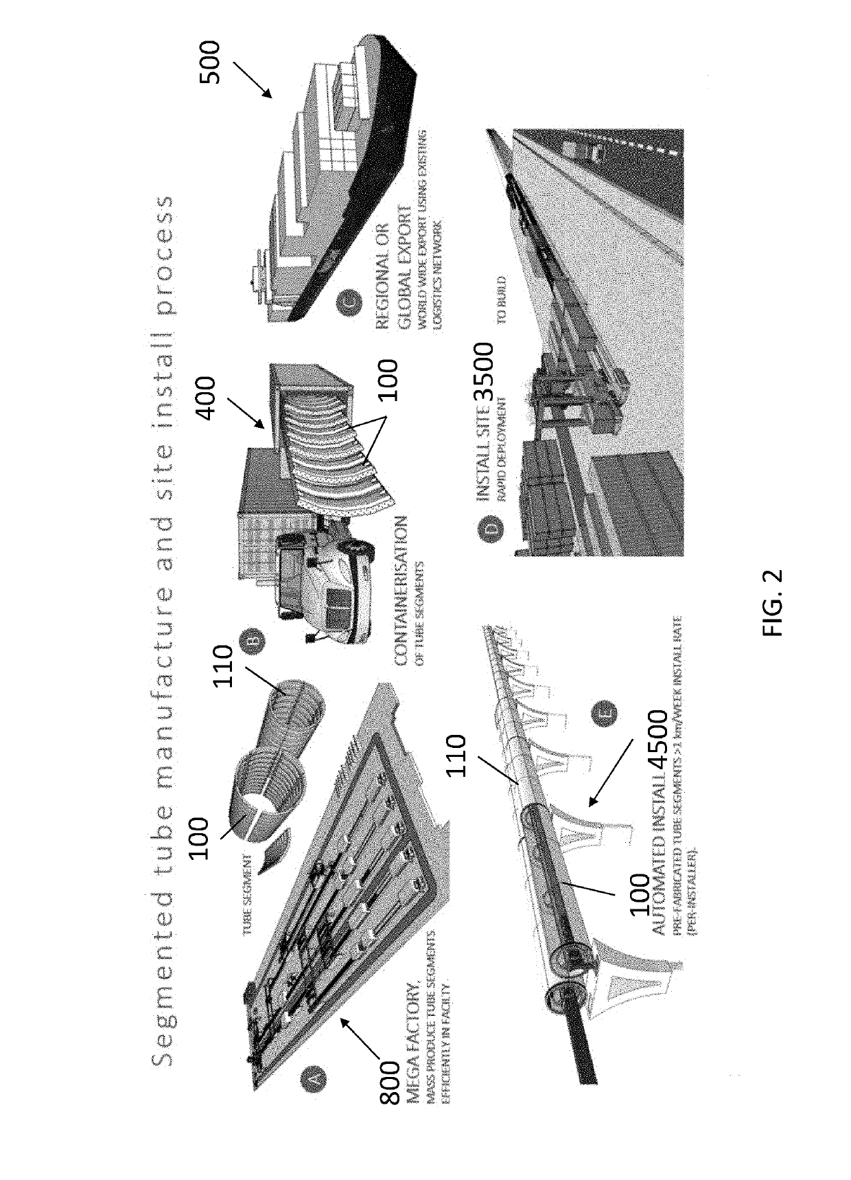
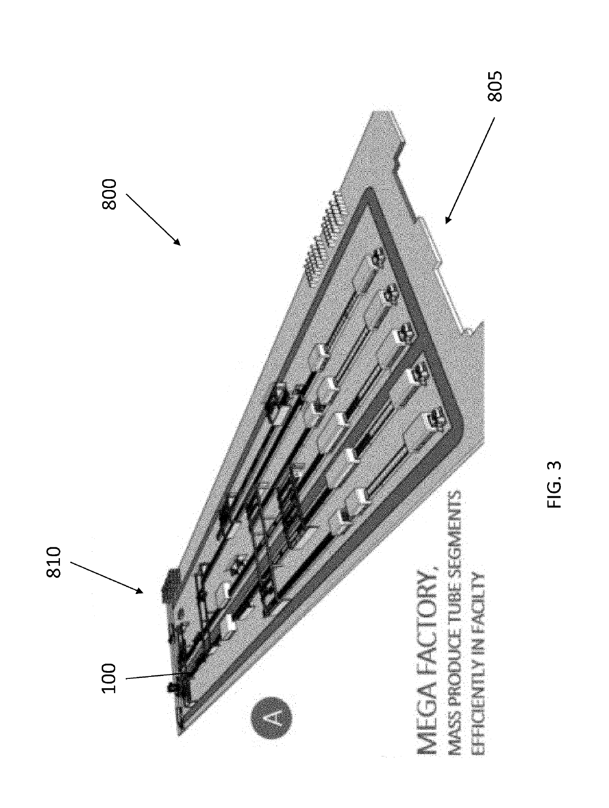
The patent is about a new way to ship and assemble tubular segments for hyperloop transportation systems. By using a central manufacturing facility, the quality control and tolerances can be maintained, reducing construction time and cost. The tubular segments can be nested within each other and shipped in shipping containers, reducing transportation costs and allowing for faster deployment. The patent also describes a variety of terrains where the tubular structure can be manufactured, assembled, and deployed. The centralized manufacture and mass production techniques can save money and improve quality. Overall, the patent presents a new way to ship and assemble tubular segments for hyperloop transportation systems that is cost-effective and efficient.

Problems solved by technology

Deployment of conventionally manufactured pipelines (or tubes) can be expensive and time consuming.
Making pipes in smaller segments may make the segments easier to ship, but more difficult or involved to assemble.
Conversely, longer segments of pipes may make assembly easier (e.g., less connections), but may render shipment and logistics more difficult.
Additionally, both techniques (e.g., utilizing smaller segments or larger segments) require a large footprint at the installation site for staging (as the tube segments must be stored on site prior to connection to the pipeline (or tube structure).

Method used


Image

  • Segmental tubes
  • Segmental tubes
  • Segmental tubes

Examples


Embodiment Construction

[0005]The novel features which are characteristic of the disclosure, both as to structure and method of operation thereof, together with further aims and advantages thereof, will be understood from the following description, considered in connection with the accompanying drawings, in which embodiments of the disclosure are illustrated by way of example. It is to be expressly understood, however, that the drawings are for the purpose of illustration and description only, and they are not intended as a definition of the limits of the disclosure.

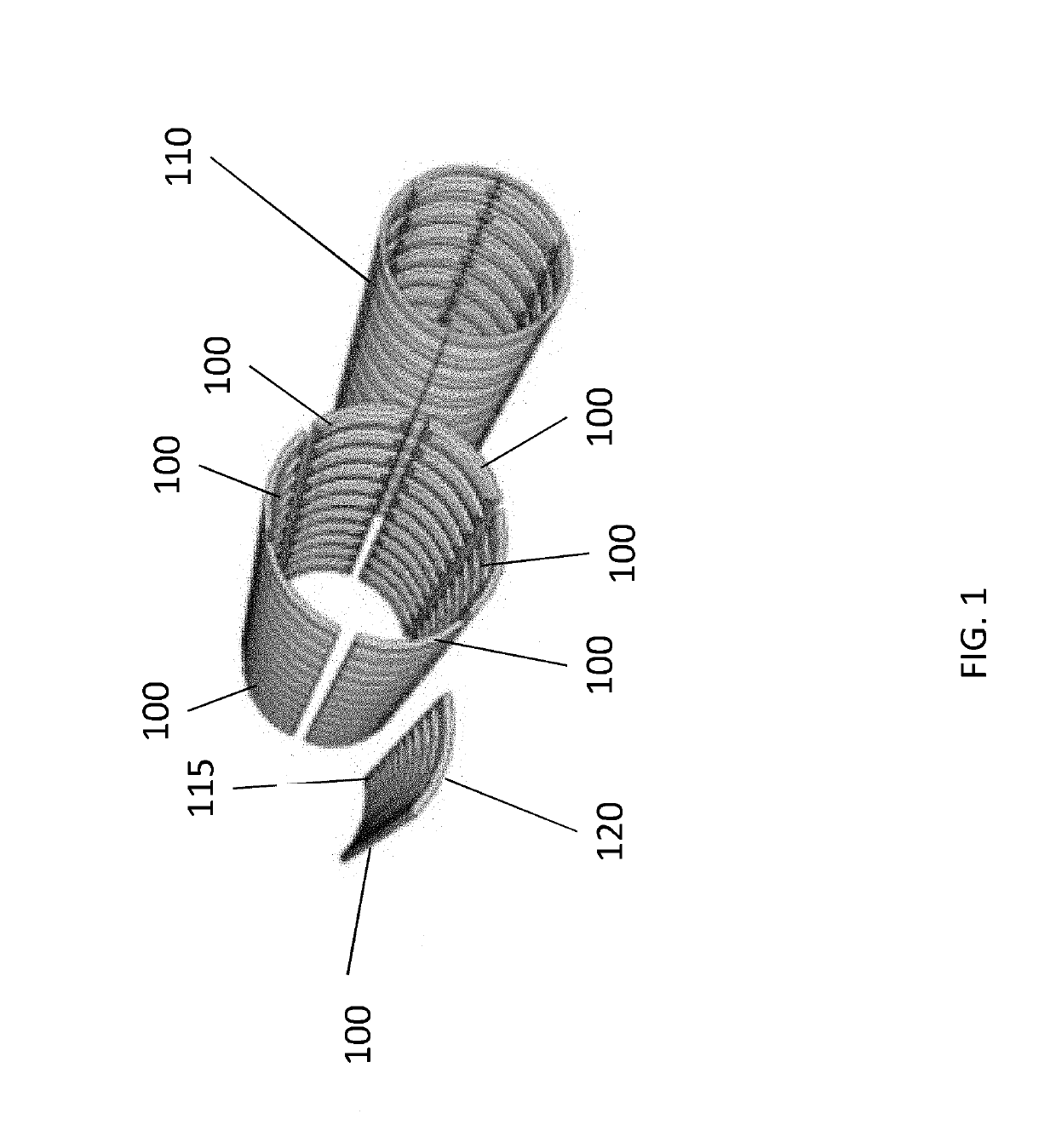
[0006]Aspects of the disclosure are directed to a segmental tube section structure having a length and a circumference. The segmental tube section structure comprises a plurality of tube segments extending the length in a longitudinal direction of the segmental tube section structure and extending in a circumferential direction of the segmental tube section structure. Each tube segment of the plurality of tube segments extends in the circumfere...


PUM


Abstract

A segmental tube section structure having a length and a circumference, the segmental tube section structure including a plurality of tube segments extending the length in a longitudinal direction of the segmental tube section structure and extending in a circumferential direction of the segmental tube section structure, wherein each tube segment of the plurality of tube segments extends in the circumferential direction to span an equal arc of the circumference of the segmental tube section, and wherein each of the plurality of tube segments are connected to adjacent tube segments of the plurality of tube segments in the circumferential direction to form the segmental tube section structure.

Description

CROSS-REFERENCE TO RELATED APPLICATION[0001]The present application claims the benefit of U.S. Provisional Application No. 62 / 593,489, filed Dec. 1, 2017, the contents of which are expressly incorporated herein by reference in their entirety.BACKGROUND OF THE DISCLOSURE1. Field of the Disclosure[0002]The present disclosure relates to tubular structures, and more specifically relates to manufacture and deployment of segmental tubes.2. Background of the Disclosure[0003]Deployment of conventionally manufactured pipelines (or tubes) can be expensive and time consuming. Generally, the pipes are produced in long spans (e.g., pre-manufactured concrete or metal tubes) that need to be shipped to the job site, and then connected by known techniques, such as welding. Making pipes in smaller segments may make the segments easier to ship, but more difficult or involved to assemble. Conversely, longer segments of pipes may make assembly easier (e.g., less connections), but may render shipment and...

Claims


Application Information

Patent Timeline
Patent Type & Authority Applications(United States)
IPC IPC(8): F16L9/22F16L1/024F16L9/02B21D51/10E01B19/00
CPCF16L9/22F16L1/0243F16L9/02B21D51/10E01B19/00B23K2101/06E04C3/00F16L9/00F16L9/17E01B25/00B61B13/10E21D11/14B23P23/06
Inventor HILGERS, ANDYRENEAU, RYAN MATTHEWMATSUMOTO, MATTHEW THOMASMEY, MATTHEW ALLANCHAVAN, SUSHANT
Owner HYPERLOOP TECH INC
Learn More