Method Of Manufacturing A Filter Element

a filter element and manufacturing method technology, applied in the direction of gravity filters, loose filtering materials, lamination filters, etc., can solve the problems of cumbersome and expensive manufacturing of filter elements according to this prior ar

Inactive Publication Date: 2008-01-24
NORDIC AIR FILTRATION
View PDF24 Cites 3 Cited by
  • Summary
  • Abstract
  • Description
  • Claims
  • Application Information

AI Technical Summary

Benefits of technology

[0005] The invention provides a filter element where it is possible to apply a liquid mass to the surface of the

Problems solved by technology

However, manufacture of a filter element accordi

Method used


Image

  • Method Of Manufacturing A Filter Element
  • Method Of Manufacturing A Filter Element
  • Method Of Manufacturing A Filter Element

Examples


Embodiment Construction

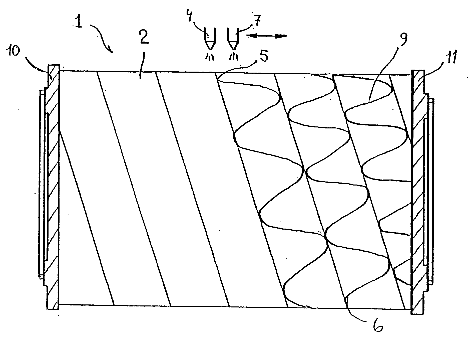
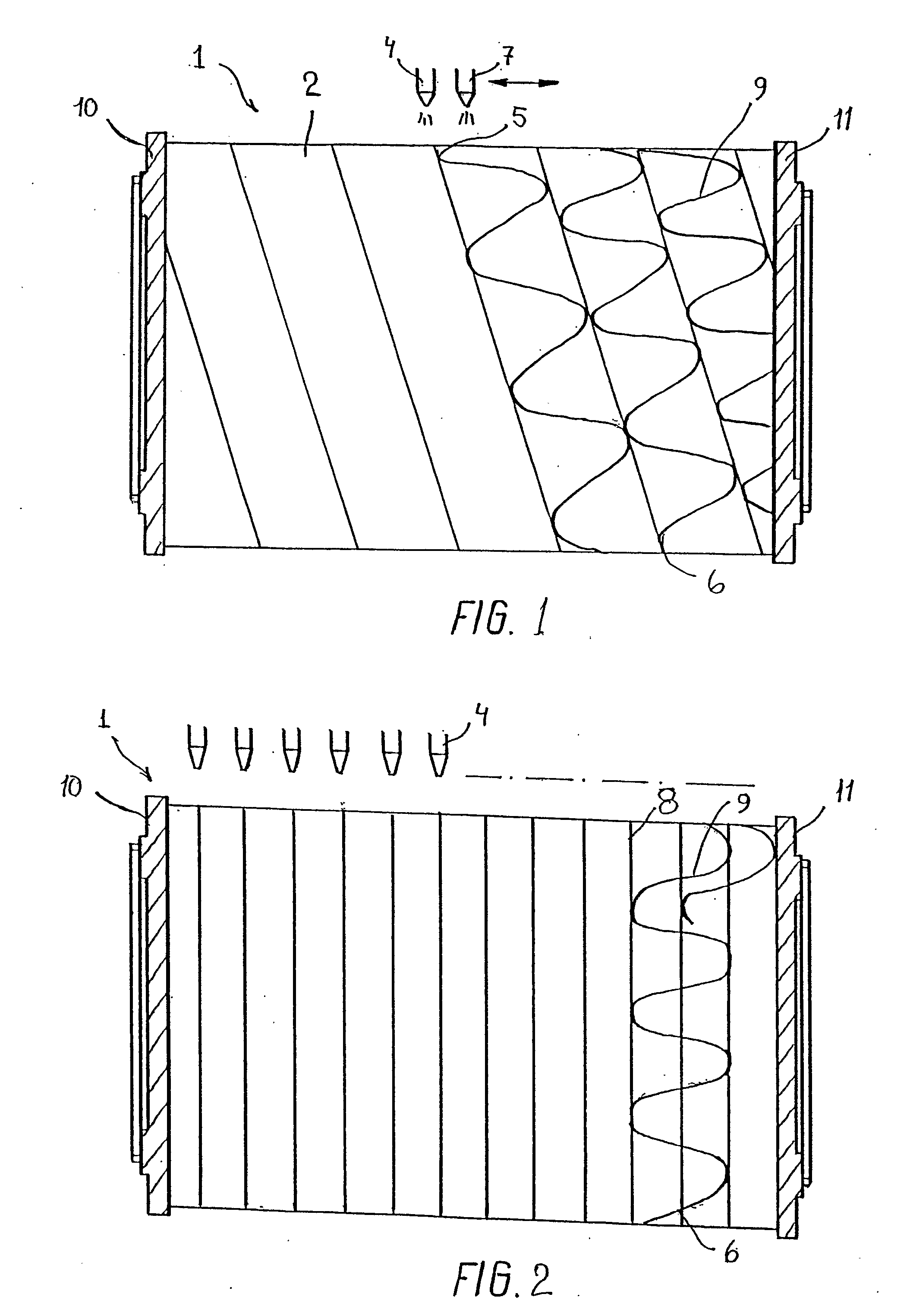
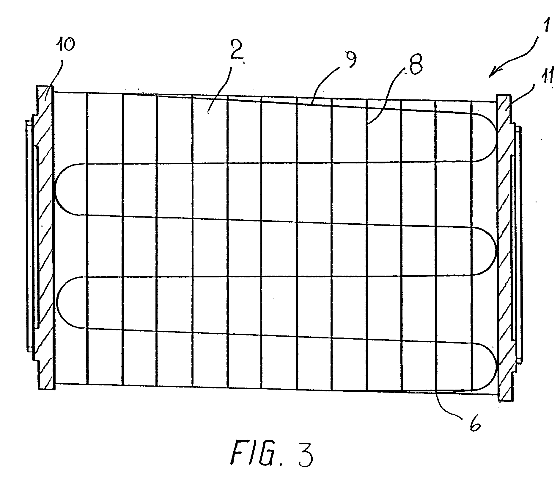
[0015] Expedient embodiments of the invention will be described below with reference to the drawing. A filter element 1 manufactured according to the method comprises a hollow outer insert 2 in which a hollow inner insert is arranged. in this exemplary embodiment, both the outer insert 2 and the inner insert are tubular with coinciding centre lines.

[0016] The outer insert 2 is composed of a base material comprising a filter material 3 made of a resin / material, e.g. cellulose and polyester.

[0017] When the outer insert 2 is arranged concentrically relative to the inner insert 3 and they are secured mutually by means of a bottom flange 10 and a top flange 11, a liquid mass 5 is applied by means of a form of nozzle 4 or the like which hardens by cooling or any other impact and is thus capable of providing the stiffening 6 necessary for the filter element 1.

[0018] The top and bottom flanges 11, 10 may either be made of a relatively resilient material, which per se may constitute a sea...


PUM

PropertyMeasurementUnit
Massaaaaaaaaaa
Combustionaaaaaaaaaa

Abstract

The invention relates to a method of manufacturing a filter element for use in connection with e.g. gas turbines and comprising a hollow outer insert in which a hollow inner insert is arranged centrally relative to the outer insert, said inserts comprising end edges to which a top flange is secured at one end, said inserts being stiffened by a net (6), said net (6) being made by applying a liquid mass (5) to the outer and/or inner side of the filter element (I) by means of one or more nozzles (4, 6), said nozzles (4,7) being movable relative to the filter element (1), one or more nozzles (4, 7) being stationary in the longitudinal direction of the filter element (1) during the application of moulding mass (5) in one or more rings (8), while the filter element (1) rotates a number of rotations about its longitudinal axis, on which one or more nozzles (4, 7) oscillate with an oscillation greater than or equal to the distance between two rings (8) and smaller than or equal to the length of the filter element (1) for the application of connecting lines (9) between the rings (8). The invention also relates to a filter element (1) manufactured by the method, wherein the stiffening (6) of the filter element (1) is formed by a solidified moulding mass (5), and the filter element (1) is made of combustible materials.

Description

THE PRIOR ART [0001] The present invention relates to a method of manufacturing a filter element for use in connection with e.g. gas turbines and comprising a hollow outer insert in which a hollow inner insert is arranged centrally relative to the outer insert, said inserts comprising end edges to which a top flange is secured, said inserts being stiffened by a net. [0002] The invention also relates to a filter element manufactured by the method. [0003] DK Patent 174840 discloses a filter element in which all the components are made of materials which may be disposed of in an environmentally friendly manner after completed use of the filter. In this known filter element, the filter element is stiffened so that at least one insert is composed of a base material to which a net is attached by means of one or more hot-melt lines or points. The base material and the net are made of combustible materials. [0004] However, manufacture of a filter element according to this prior art is cumbe...

Claims


Application Information

Patent Timeline
IPC IPC(8): B01D46/24B01D46/00
CPCB01D46/2411B01D46/0001
Inventor POULSEN, JORGEN
Owner NORDIC AIR FILTRATION
Why Eureka
Try Eureka