Movable type magnetic suspension apparatus

a magnetic suspension and moving technology, applied in the direction of conveyors, conveyors, non-mechanical conveyors, etc., can solve the problem of limit on the application field of the magnetic suspension apparatus

Active Publication Date: 2019-11-12
ZHAOQING HENGYI INDAL
View PDF9 Cites 0 Cited by
  • Summary
  • Abstract
  • Description
  • Claims
  • Application Information

AI Technical Summary

Benefits of technology

[0013]In some embodiments of the present disclosure, the magnetic suspension base has a first critical anti-horizontal deviation mechanism, the suspension body has a second critical anti-horizontal deviation mechanism, the first critical anti-horizontal deviation mechanism and the second critical anti-horizontal deviation mechanism are configured to mate with each other so as to prevent the suspension body from excessive horizontal deviation that would cause failure of normal suspension of the suspension body when the suspension body is located on the magnetic suspension base and when the suspension body is at a suspension critical point while the magnetic suspension mechanism rises.
[0055]The magnetic suspension apparatus according to the present disclosure enables the suspension body to change spatial positions in a suspended state, and thereby substantially expands application fields of the magnetic suspension apparatus.

Problems solved by technology

However, in the known magnetic suspension apparatus, the base usually remains stationary and the suspension body can only suspend at a specific position; in addition, it is still necessary to manually complete an aligned suspension procedure of the suspension body, which results in limitation on application fields of the magnetic suspension apparatus.

Method used


Image

  • Movable type magnetic suspension apparatus
  • Movable type magnetic suspension apparatus
  • Movable type magnetic suspension apparatus

Examples


Embodiment Construction

[0065]The present disclosure will be further described below in conjunction with embodiments and figures. Those skilled in the art should appreciate that embodiments and figures are only intended to facilitate better understanding of the present disclosure and not to impose any limitations.

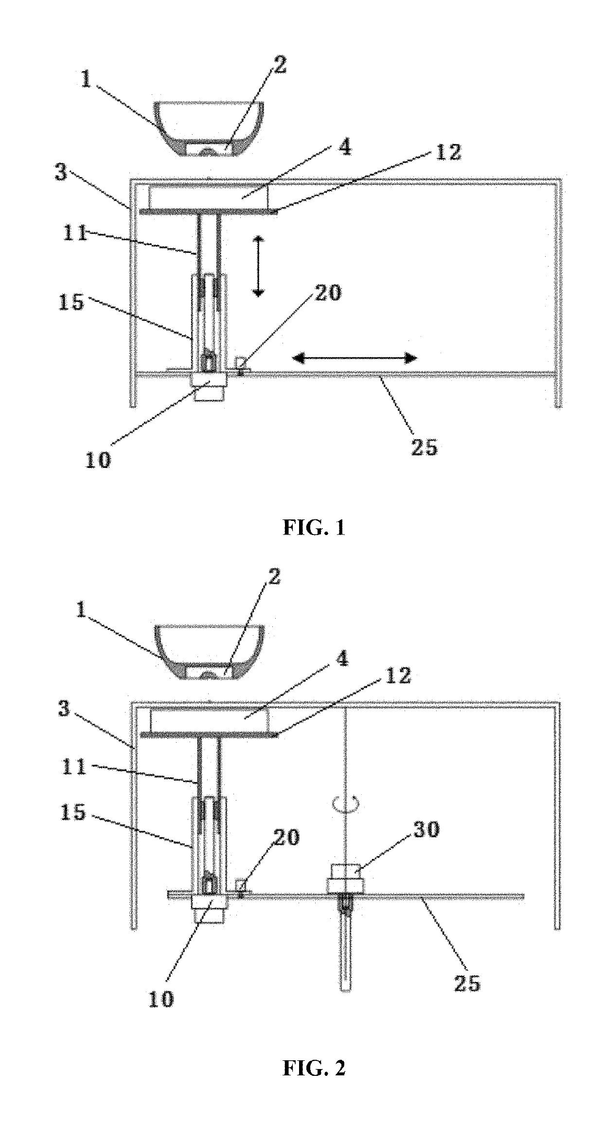
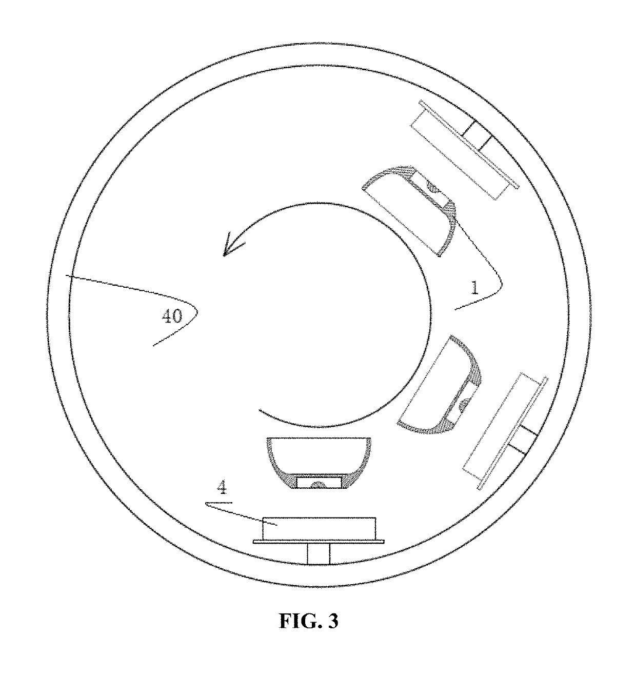
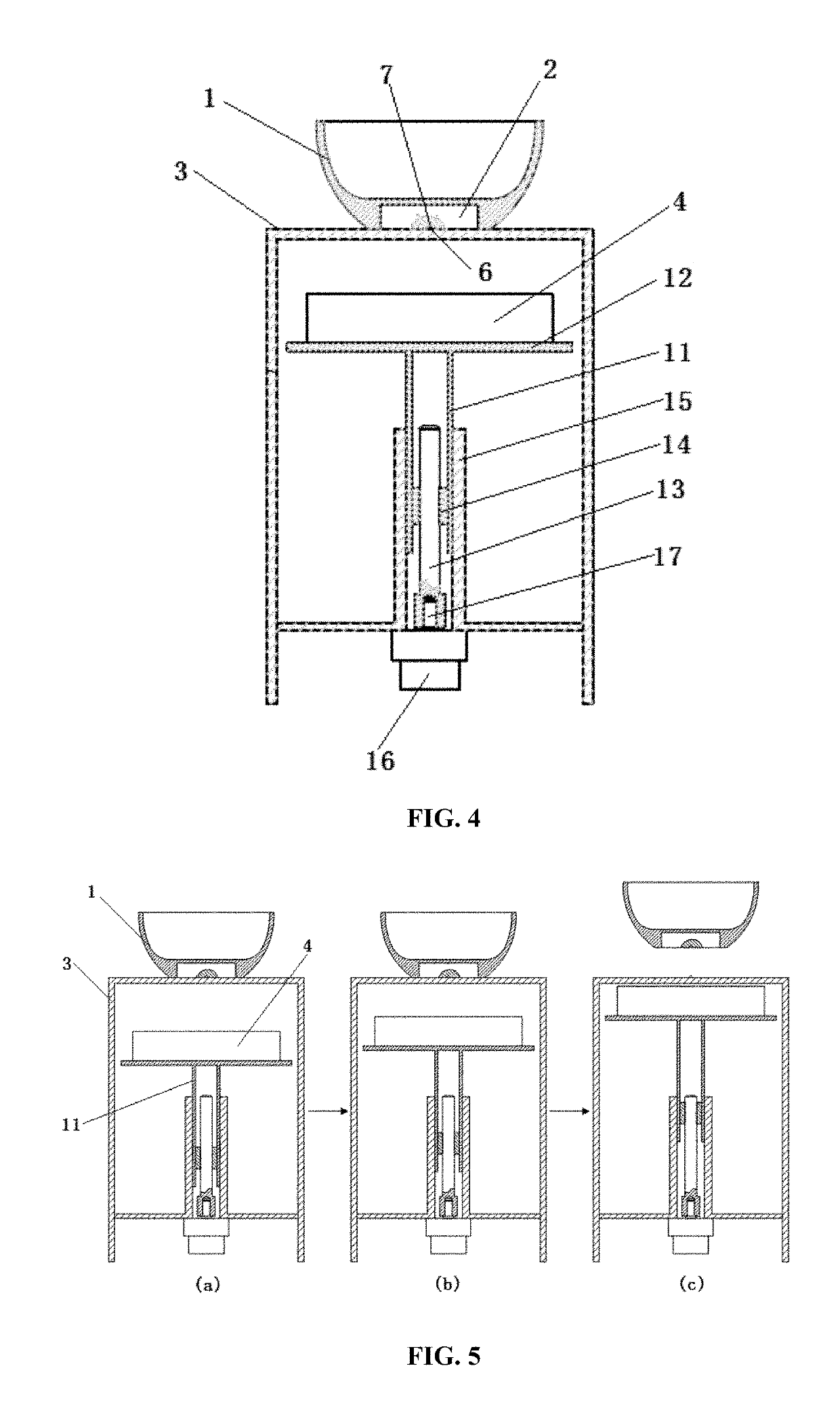
[0066]Referring to FIG. 1, a movable type magnetic suspension apparatus according to the present disclosure mainly comprises a suspension body 1 and a magnetic suspension base 3. The suspension body 1 is initially located on the magnetic suspension base 3 and will suspend or float over the magnetic suspension base 3. The suspension body 1 comprises a magnet 2 which is preferably a permanent magnet. A shape of the magnet 2 may be set according to the needs of the suspension body 1, for example, the shape may be cylindrical, stepped, truncated conical or the like. The magnet 2 may be a whole magnet or formed by putting multiple magnets together.

[0067]The magnetic suspension base 3 has a magnetic sus...


PUM


Abstract

Disclosed is a movable type magnetic suspension apparatus, comprising: a suspension body (1) having a magnet (2); and a magnetic suspension base (3), the magnetic suspension base comprising: a magnetic suspension mechanism (4) for suspending the suspension body at a predetermined distance thereabove; and a displacement mechanism for displacing the magnetic suspension mechanism to cause the suspension body in a suspended state to displace. The movable type magnetic suspension apparatus enables the suspension body to move in air along a predetermined trajectory and can substantially expand application fields of the magnetic suspension apparatus.

Description

FIELD OF THE DISCLOSURE[0001]The present disclosure generally relates to the field of magnetic suspension apparatus, and specifically to a magnetic suspension apparatus whose suspension body changes position in space.BACKGROUND OF THE DISCLOSURE[0002]A known magnetic suspension apparatus such as a magnetic suspension desk lamp or a magnetic suspension gyroscope generally includes a base and a suspension body, the base and the suspension body both include a magnet, and the magnet in the base, through magnetic action (e.g., magnetic repulsion force), can make the suspension body suspend at a predetermined distance above the base, thereby generating a floating fantastic visual effect and appealing to people.[0003]However, in the known magnetic suspension apparatus, the base usually remains stationary and the suspension body can only suspend at a specific position; in addition, it is still necessary to manually complete an aligned suspension procedure of the suspension body, which resul...

Claims


Application Information

Patent Timeline
Patent Type & Authority Patents(United States)
IPC IPC(8): H02K7/09B65G54/02H02N15/00
CPCH02N15/00B65G54/02
Inventor LI, CAILIWANG, YUNCHUANWANG, XIAOBINGLI, LIANGQING
Owner ZHAOQING HENGYI INDAL
Why Eureka
Try Eureka