Vehicle camera system with image manipulation

a camera system and vehicle technology, applied in the field of vehicle vision systems, can solve problems such as the inability of the camera system to provide video

Active Publication Date: 2019-12-03
MAGNA ELECTRONICS
View PDF299 Cites 3 Cited by
  • Summary
  • Abstract
  • Description
  • Claims
  • Application Information

AI Technical Summary

Problems solved by technology

However, a typical vehicle camera system may not be able to provide video that is quickly and reliably comprehensible to the driver.

Method used


Image

  • Vehicle camera system with image manipulation
  • Vehicle camera system with image manipulation
  • Vehicle camera system with image manipulation

Examples


Embodiment Construction

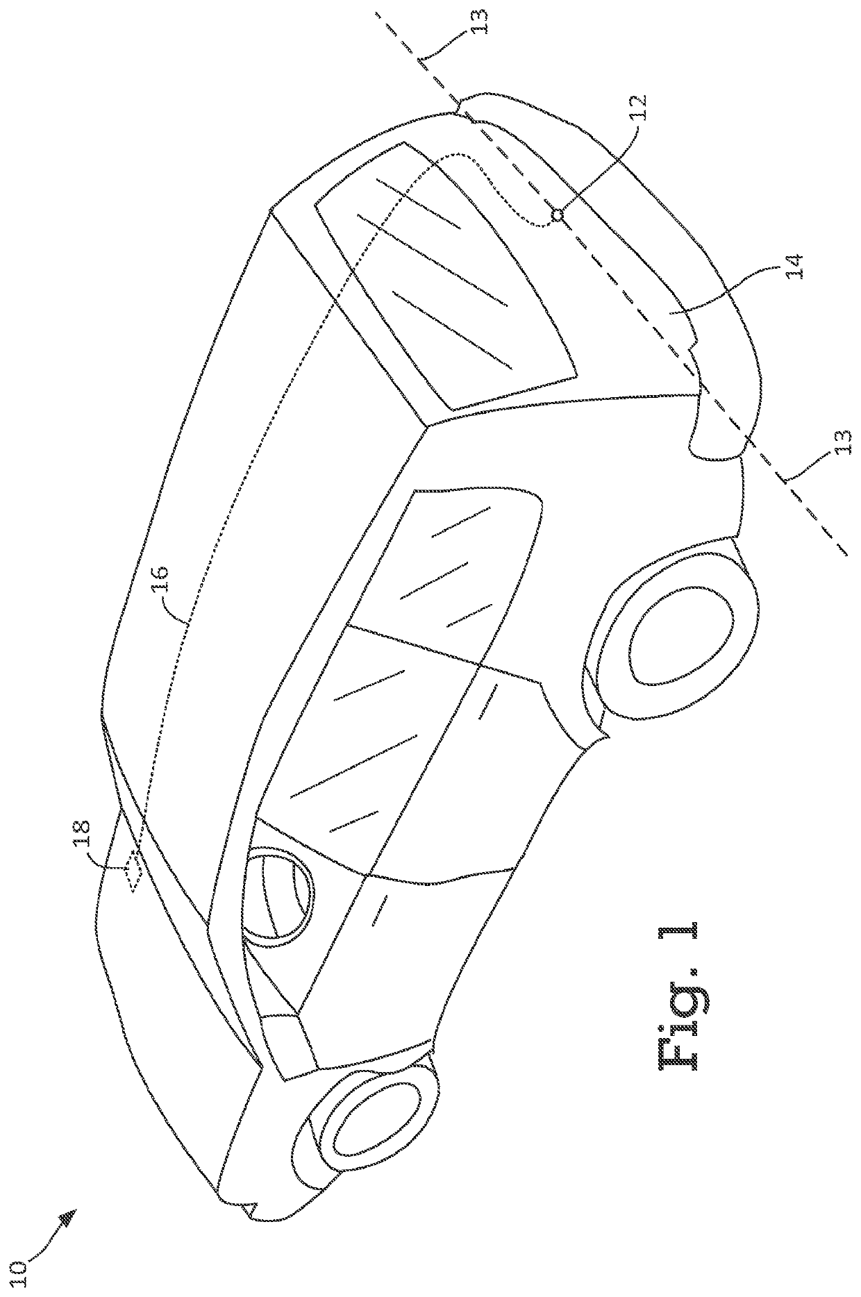
[0016]Referring now to the drawings and the illustrative embodiments depicted therein, and with reference to FIG. 1, a vehicle 10, such as a car, truck, van, bus, or other type of vehicle, includes a camera 12. The camera 12 is configured to be positioned on the vehicle 12 to face away from the bulk of the body 14 of the vehicle 10 to capture video of the environment outside of the vehicle 10 to, for example, aid the operator of the vehicle 10, such as, for example, when executing a reversing maneuver or a parking maneuver of the vehicle.

[0017]In this example, the camera 12 is positioned at a rear-portion of the body 14 of the vehicle 10 and is rear-facing to capture video of the scene behind the vehicle 12. In another example, the camera 12 can be positioned at a rear bumper of the vehicle 10. In still other examples, the camera can be forward-facing and can be positioned, for example, at the front windshield, at the rear-view mirror, or at the grille of the vehicle 10. For example...


PUM


Abstract

An image, such as a frame of video, is captured by a single camera positioned on a vehicle to capture a scene external to the vehicle. A first image manipulation is performed on a first region of the image to generate a first manipulated region. A second image manipulation is performed on a second region of the image to generate a second manipulated region. The second region is different from the first region. The second image manipulation is different from the first image manipulation. A manipulated image including the first manipulated region and the second manipulated region is generated by a processor and displayed on a display in the cabin of the vehicle. In this way, central, left, and right regions of the image can be manipulated differently to aid the driver of the vehicle.

Description

CROSS REFERENCE TO RELATED APPLICATIONS[0001]The present application is a 371 national phase filing of PCT Application No. PCT / US2013 / 027342, filed Feb. 22, 2013, which claims the filing benefit of U.S. provisional application, Ser. No. 61 / 601,669, filed Feb. 22, 2012, which is hereby incorporated herein by reference in its entirety.FIELD OF THE INVENTION[0002]This disclosure relates to vehicle vision systems and, more particularly, to a vehicle vision system that displays images derived from image data captured by one or more vehicle cameras.BACKGROUND OF THE INVENTION[0003]Vehicle camera systems can provide vehicle operators with valuable information about driving conditions. For example, a typical vehicle camera system can aid a driver in parking her automobile by alerting her to hazards around her automobile that should be avoided. Other uses for vehicle camera system are also known. However, a typical vehicle camera system may not be able to provide video that is quickly and re...

Claims


Application Information

Patent Timeline
Patent Type & Authority Patents(United States)
IPC IPC(8): B60R1/00
CPCB60R1/00B60R2300/8066B60R2300/8093B60R2300/305B60R2300/802B60R2300/306
Inventor LU, YUESHENG
Owner MAGNA ELECTRONICS
Why Eureka
Try Eureka