Carry measuring device, hit-ball-direction measuring device, carry measuring system, carry measuring method, hit-ball determining device, hit-ball determining system, hit-ball determining method, and recording medium

a technology of hitting ball and measuring device, which is applied in the field of hitting ball determining device, hitting ball determining system, hitting ball determining method, etc., can solve the problems such as the inability to calculate the index such as the fairway keep ratio based on the position of the hit ball, accumulation of calculation errors, etc., and achieves the effect of easy and accurate determination of the stop position of the ball

Active Publication Date: 2019-12-17
SEIKO EPSON CORP
View PDF26 Cites 0 Cited by
  • Summary
  • Abstract
  • Description
  • Claims
  • Application Information

AI Technical Summary

Benefits of technology

[0009]Another advantage of some aspects of the invention is to easily and accurately determine the position of a hit ball without work of a player.
[0035]Still yet further another aspect of the invention is directed to a recording medium having recorded therein a computer program for causing a computer to execute: acquiring a sensor signal from a motion sensor attached to at least one of an exercise instrument and a user; acquiring position information; acquiring map information including a plurality of areas; detecting a shot on the basis of the sensor signal; measuring a shot position on the basis of the position information at the time when the shot is detected; and determining in which of the plurality of areas the shot position is included. Consequently, it is possible to easily and accurately determine a stop position of a ball and an area of the stop position of the ball without work of a player.

Problems solved by technology

As a cause of the deviation, for example, accumulation of calculation errors due to the integration and the influence of weather conditions such as wind on a hit ball are conceivable.
This is extremely troublesome and sometimes causes an error.
Further, indexes such as the fairway keep ratio based on the position of the hit ball cannot be calculated.

Method used


Image

  • Carry measuring device, hit-ball-direction measuring device, carry  measuring system, carry measuring method, hit-ball determining device, hit-ball determining system, hit-ball determining method, and recording medium
  • Carry measuring device, hit-ball-direction measuring device, carry  measuring system, carry measuring method, hit-ball determining device, hit-ball determining system, hit-ball determining method, and recording medium
  • Carry measuring device, hit-ball-direction measuring device, carry  measuring system, carry measuring method, hit-ball determining device, hit-ball determining system, hit-ball determining method, and recording medium

Examples


first embodiment

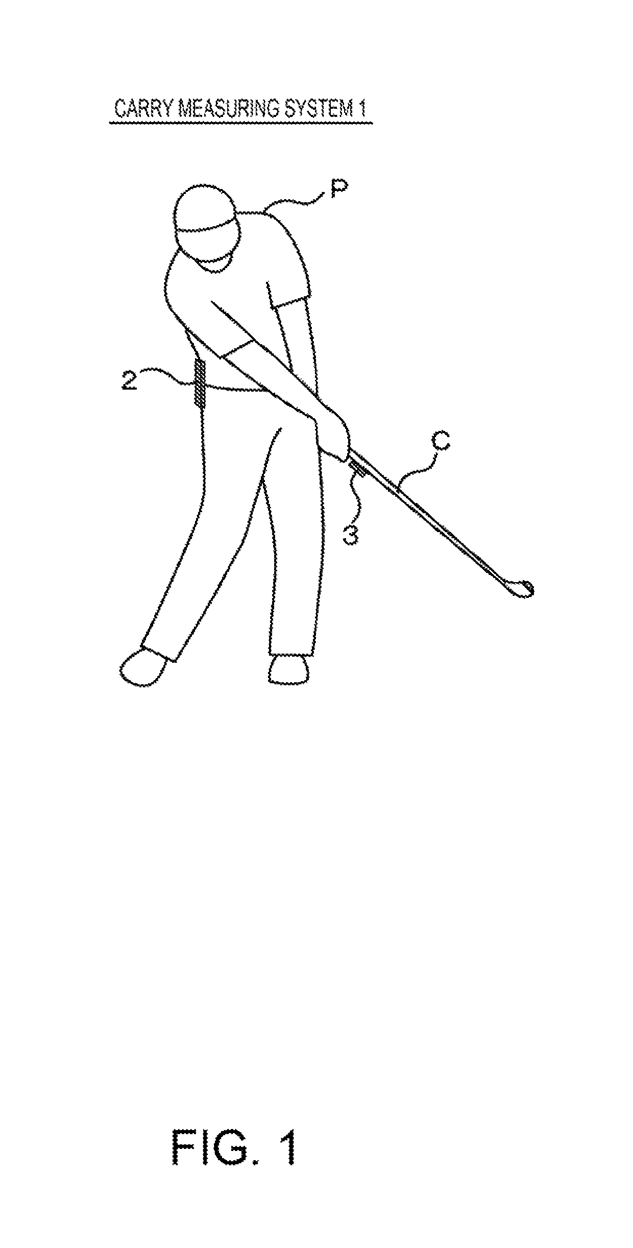
[0058]FIG. 1 is a diagram showing an example of the exterior of a carry measuring system according to a first embodiment of the invention.

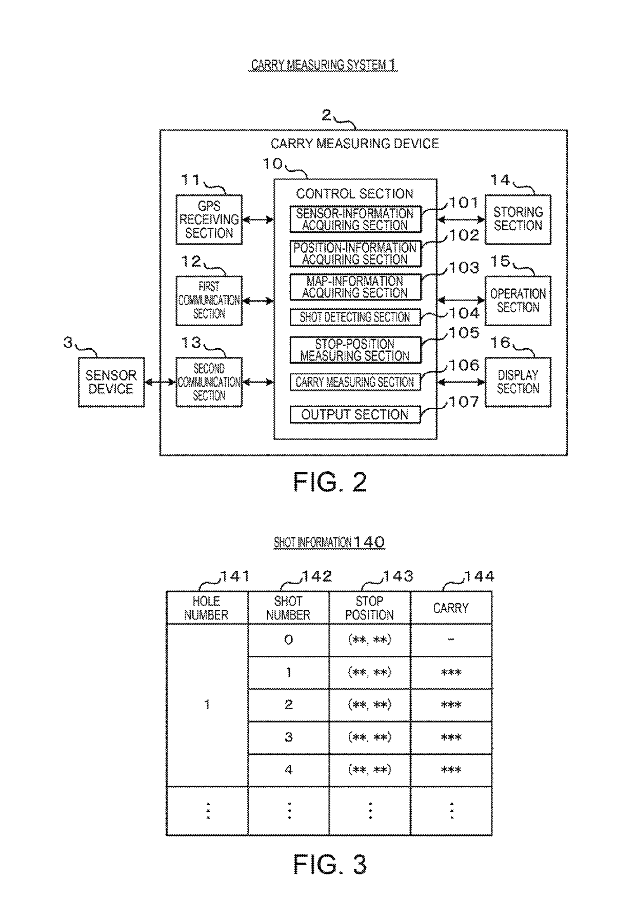
[0059]A carry measuring system 1 includes a carry measuring device 2 and a sensor device 3. The carry measuring device 2 and the sensor device 3 are communicably connected to each other by wire or radio. In the example shown in FIG. 1, the carry measuring device 2 is attached to the waist of a user P. The sensor device 3 is attached to a club C. Naturally, an attaching position of the carry measuring device 2 is not particularly limited and may be, for example, the back or the leg of the user P, the club C, or the like. An attaching position of the sensor device 3 is not particularly limited and may be, for example, the back of the hand or the wrist of the user P or the like.

[0060]The carry measuring device 2 detects, on the basis of a signal output from the sensor device 3, a swing during a shot performed by the user P using the club C. In this e...

second embodiment

[0107]In a second embodiment, in addition to a ball stop position and a carry of a shot, a hit ball direction of the shot is calculated. In the following explanation, components same as the components in the first embodiment are denoted by the same reference numerals and signs and explanation of the components is omitted. Differences from the first embodiment are mainly explained.

[0108]FIG. 6 is a block diagram showing an example of the configuration of a carry measuring system according to a second embodiment of the invention.

[0109]The carry measuring device 2 includes a sensor section 17 in addition to the sections explained in the first embodiment. The control section 10 includes a hit-ball-direction measuring section 108.

[0110]The sensor section 17 includes a magnetic sensor (which may be referred to as orientation sensor as well) that detects terrestrial magnetism and outputs a signal. The magnetic sensor detects, for example, terrestrial magnetisms of two axes (an x axis: the ...

third embodiment

[0126]In a third embodiment, in addition to a ball stop position and a carry of a shot and a hit ball direction, an area where a ball flown by the shot is located is calculated.

[0127]FIG. 11 is a diagram showing an example of the exterior of a hit-ball determining system according to the third embodiment of the invention. In the following explanation, the hit-ball determining system according to this embodiment is explained with reference to the drawings. Note that components same as the components in the embodiments explained above are denoted by the same reference numerals and signs and redundant explanation of the components is omitted.

[0128]In FIG. 11, a hit-ball determining system 51 includes a hit-ball determining device 52 and the sensor device 3. The hit-ball determining device 52 and the sensor device 3 are communicably connected to each other by wire or radio. In the example shown in FIG. 11, the hit-ball determining device 52 is attached to the waist of the user P and the...


PUM


Abstract

A carry measuring device includes a first acquiring section configured to acquire a sensor signal from a motion sensor attached to at least one of an exercise instrument and a user, a second acquiring section configured to acquire position information, a shot detecting section configured to detect a shot on the basis of the sensor signal, a position measuring section configured to measure a shot position on the basis of the position information at the time when the shot is detected, and a carry measuring section configured to measure a carry of a hit ball on the basis of the distance between the shot position of the last time and the shot position of this time.

Description

BACKGROUND[0001]1. Technical Field[0002]The present invention relates to a carry measuring device, a hit-ball-direction measuring method, a carry measuring system, a carry measuring method, a hit-ball determining device, a hit-ball determining system, a hit-ball determining method, and a recording medium.[0003]2. Related Art[0004]JP-A-10-43349 (Patent Literature 1) describes a swing diagnosis device that determines a hit ball direction and a carry of a hit ball on the basis of acceleration at impact time of a swing (a shot) obtained from an acceleration sensor attached to the back of the hand of a human.[0005]However, in Patent Literature 1, a hit ball direction and a hit ball carry are estimated by integrating the acceleration at the impact time of the swing. Estimated values of the hit ball direction and the hit ball carry often deviate from an actual hit ball direction and an actual hit ball carry. As a cause of the deviation, for example, accumulation of calculation errors due t...

Claims


Application Information

Patent Timeline
Patent Type & Authority Patents(United States)
IPC IPC(8): A63B24/00G06K9/00
CPCG06K9/00342G06V40/23
Inventor NATORI, YOICHINAKAJO, SHOICHITANAKA, HISAO
Owner SEIKO EPSON CORP
Why Eureka
Try Eureka