Removal tool

a technology of removal tool and clamping member, which is applied in the field of removal tool, can solve the problems of not being able to replace the clamping member in a simple way, and achieve the effect of facilitating removal work

Active Publication Date: 2020-03-10
YANG JEN YUNG
View PDF10 Cites 3 Cited by
  • Summary
  • Abstract
  • Description
  • Claims
  • Application Information

AI Technical Summary

Benefits of technology

[0004]Therefore, a main objective of the present invention is to provide a removal tool, so that insertion bodies having different sizes can be replaced in a simple manner, to facilitate removal work.

Problems solved by technology

Therefore, there is still no simple operation of replacing different clamping members.

Method used


Image

  • Removal tool
  • Removal tool
  • Removal tool

Examples


Embodiment Construction

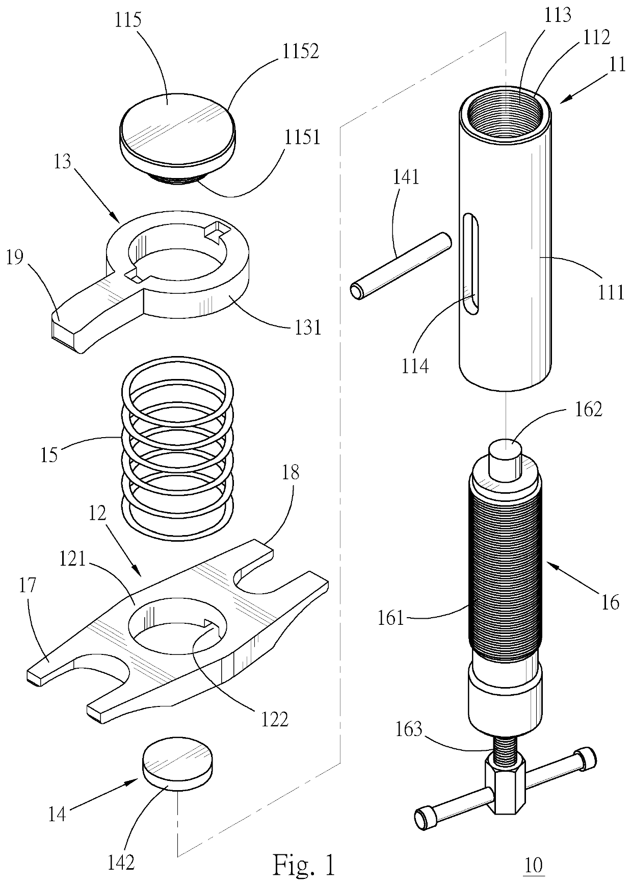
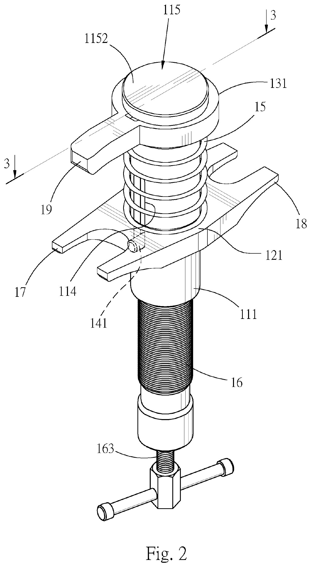
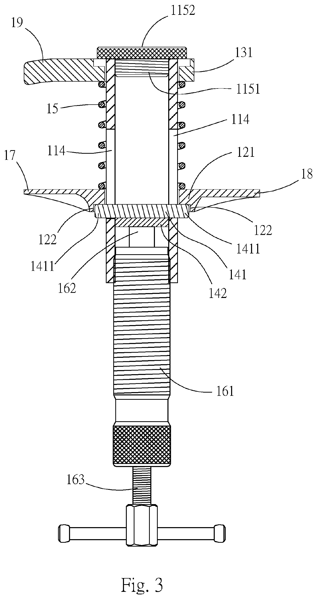
[0022]First, referring to FIG. 1 to FIG. 4, a removal tool (10) provided in a first preferred embodiment of the present invention mainly includes a base portion (11), a first component (12), a second component (13), a transmission portion (14), an elastic portion (15), a driving portion (16), a first acting portion (17), a second acting portion (18), and a third acting portion (19).

[0023]The base portion (11) has a cylindrical column body (111). A sliding space (112) extends through two ends of the column axis of the column body (111) along a column axis of the column body (111). A thread (113) is disposed on a wall of the sliding space (112). A pair of guide holes (114) are separately disposed on two sides of the column body (111) in a coaxial manner, and extend by a suitable length along the column axis of the column body (111) in a manner of being connected to the sliding space (112). A columnar seal body (115) is coaxially located at an end of the column axis of the column body ...


PUM


Abstract

The present invention provides a removal tool. A base portion is used as a base, and a first component and a second component are separately disposed on the base portion in a manner of being isolated from each other, so that a relative distance between the first component and the second component can be changed under the effect of an external first external force, to enable a vehicle maintainer to perform removal work of separating a ball joint of a lower support arm of a vehicle from a combined bushing. The technical features of the present invention further include a first acting portion, a second acting portion, and a third acting portion respectively disposed on the first component and the second component. The first acting portion and the second acting portion are disposed on a same component, and the first component is enabled to change relative positions of the first component and the second component under the effect of an external second external force, so that relative positions among the first acting portion, the second acting portion, and the third acting portion are changed. As such, the vehicle maintainer can choose the first acting portion and the second acting portion or choose the first acting portion and the third acting portion according to an actual requirement, to adapt to requirements of different conditions of removal work.

Description

BACKGROUND OF THE INVENTION1. Field of the Invention[0001]The present invention relates to automotive maintenance tools, and in particular, to a removal tool.2. Description of the Related Art[0002]A replaceable ball joint removal tool is disclosed in the prior art ROC patent No. 1373398. By using a movable and replaceable clamping member, an operator can adapt to requirements of different ball joint specifications to replace a clamping member having a corresponding size, to provide convenience to the operator.[0003]In the removal tool disclosed in the foregoing published prior art patent, a replaceable clamping member can be used to extend the applicability of the ball joint removal tool. However, during the operation of replacing a clamping member, an original clamping member needs to be removed first before a clamping member having a different size can be clamped on the body of the tool again. Therefore, there is still no simple operation of replacing different clamping members.SU...

Claims


Application Information

Patent Timeline
Patent Type & Authority Patents(United States)
IPC IPC(8): B25B27/06B25B27/02
CPCB25B27/062B25B27/023
Inventor YANG, JEN-YUNG
Owner YANG JEN YUNG
Why Eureka
Try Eureka