
Cutting wheel for a trench cutter

a cutting wheel and cutter technology, applied in mechanical machines/dredgers, excavators, soil shifting machines/dredgers, etc., can solve the problems of wasting time and resources, and facilitating the cutting wheel or cutting tools exchange, so as to facilitate the economic and rapid making of the trench

Active Publication Date: 2015-08-25
BAUER MASCH GMBH
View PDF14 Cites 0 Cited by
  • Summary
  • Abstract
  • Description
  • Claims
  • Application Information

AI Technical Summary

Benefits of technology

The invention provides a cutting wheel and method for making a trench in the ground that are economical and rapid. The cutting wheel has chisels and cutting teeth for different ground compositions, arranged in a common peripheral row or line around the base body. The chisels and cutting teeth are mounted in separate holders, which helps in making quick transition between ground layers without changing tools. The cutting tools are angled to cover a wider area of ground and reduce wear on the cutting teeth when removing hard stone layers. A group of at least three chisels is formed in the peripheral row, which enlarges the removal region and achieves a "full cut" of ground.

Problems solved by technology

The exchange of the cutting wheels or the cutting tools requires great time and resources.

Method used


Image

  • Cutting wheel for a trench cutter
  • Cutting wheel for a trench cutter
  • Cutting wheel for a trench cutter

Examples


Embodiment Construction

[0041]The same components or those having the same effect are characterised in all the figures with the same reference symbols.

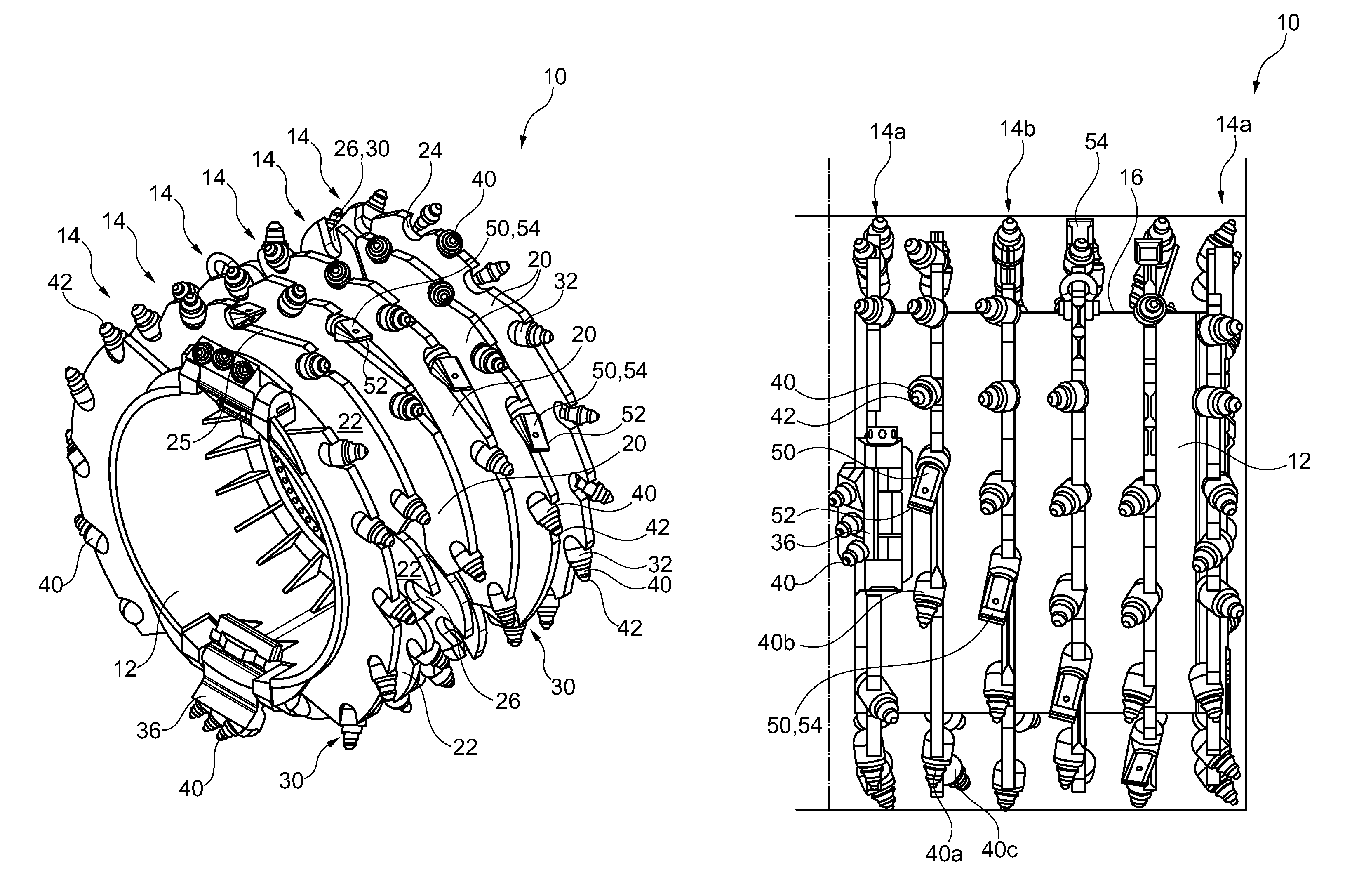
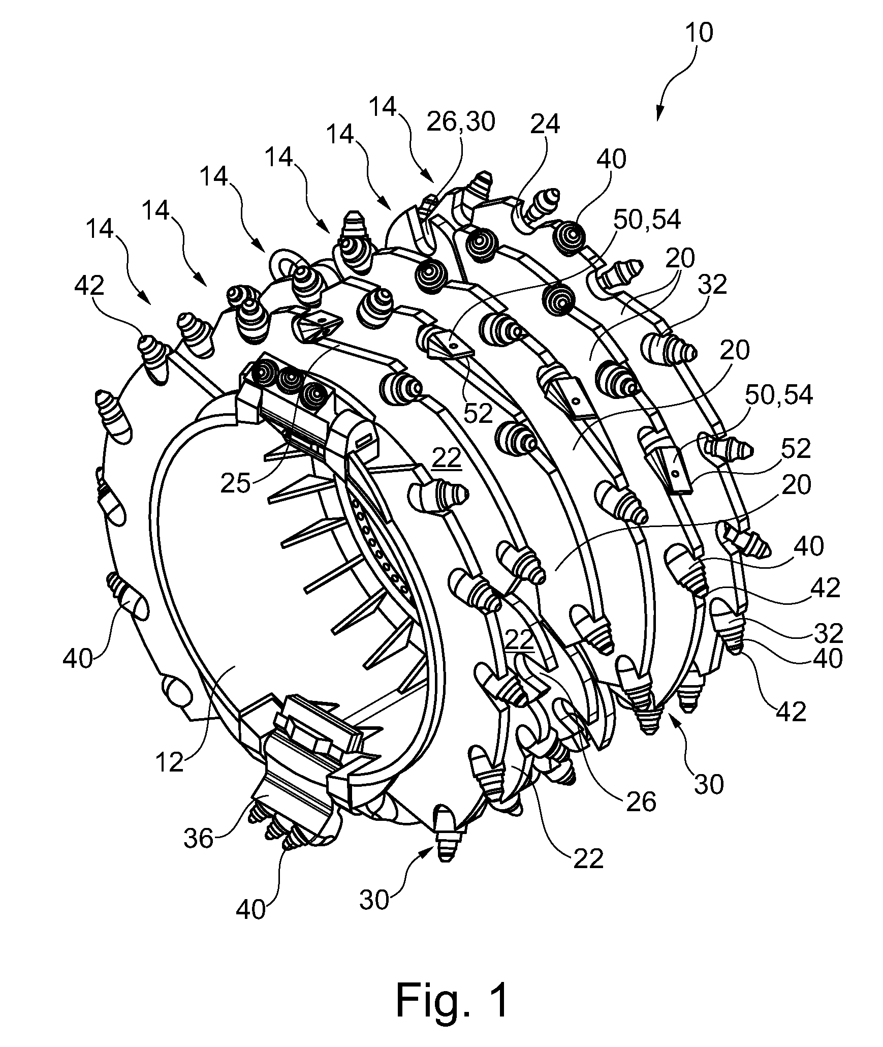
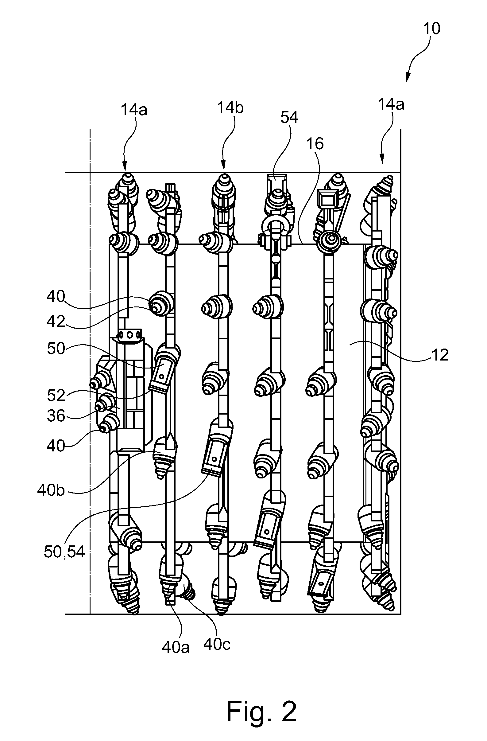
[0042]The cutting wheel 10 shown in the figures comprises a drum-like base body 12 which forms a hub of the cutting wheel. A plurality of cutting tools in the form of chisels 40 and cutting teeth 50 are provided on an outer cylindrical shell surface 16 of the cutting wheel 10 in a plurality of peripheral rows 14. In one peripheral row 14, chisels 40 and cutting teeth 50 are arranged alternately.

[0043]The cutting wheel 10 comprises a plurality of stationary, thus immovable, holders 30 for receiving and holding the cutting tools. The holders 30 are formed from sheet metal rings 20, into which receiving sockets 32 or chisel holders can be inserted to receive the cutting tools. The chisels 40 and the cutting teeth 50 are arranged in independent receiving areas separate from each other.

[0044]The annular outer jacket surface of the cutting wheel 10 carries at pred...


PUM


Abstract

The invention relates to a cutting wheel for a trench cutter with a drum-like base body, on the outer periphery of which stationary holders are arranged in at least one peripheral row, in which cutting tools for removing ground are received. In the at least one peripheral row chisels with a substantially pointed removal tip and also cutting teeth with a substantially linear cutting edge are arranged as cutting tools. The invention also relates to a method for making a trench in the ground.

Description

FIELD OF THE INVENTION[0001]The invention relates to a cutting wheel for a trench cutter and to a method for creating a trench in the ground.[0002]The cutting wheel comprises a drum-like base body, on the outer periphery of which stationary holders are arranged in at least one peripheral row, in which stationary holders cutting tools are received for removing ground elements.DESCRIPTION OF RELATED ART[0003]In order to remove ground elements, different cutting tools are known. For the removal of softer earth and stone layers, for example sandy and cohesive matters such as gravel, in most cases cutting teeth with one or more line-form cutting edges are used. The earth is released substantially by a cutting effect of the cutting edges and carried away. In contrast, in the case of harder ground materials, chisels with a substantially pointed removal tip are used. The pointed tip can break up hard material so that it is split off or chipped away. Depending upon the composition of the gro...

Claims


Application Information

Patent Timeline
IPC IPC(8): E02F5/08E02D17/13E02F3/20E02F3/24E02F9/28
CPCE02F5/08E02D17/13E02F3/205E02F3/241E02F3/248E02F9/2866E02F5/28E02F5/30
Inventor HUBER, LUDWIG ANDREAS
Owner BAUER MASCH GMBH
Learn More