Hybrid-type working machine

a working machine and hybrid technology, applied in mechanical machines/dredgers, transportation and packaging, electric propulsion mounting, etc., can solve the problems of deteriorating workability of replacement work, and achieve the effects of improving the assembling performance of the first inverter, reducing costs, and improving workability

Active Publication Date: 2017-10-17
NIHON KENKI CO LTD
View PDF13 Cites 4 Cited by
  • Summary
  • Abstract
  • Description
  • Claims
  • Application Information

AI Technical Summary

Benefits of technology

[0006]The present invention is made in view of the aforementioned problems in the conventional art, and an object of the present invention is to provide a hybrid-type working machine that can mount an inverter thereon compactly and facilitate a removal work of the inverter.
[0009]With this arrangement, the first inverter and the second inverter are mounted on the support bracket in the position different from the position where the electricity storage device is mounted. Therefore, the first inverter and the second inverter can be mounted compactly on the vehicle body through the support bracket. Along with this, it is possible to improve workability on the replacement work of the first and second inverters and the electricity storage device. Since the support bracket can elastically support the first and second inverters together on the vehicle body, it is not necessary to provide a vibration isolating member to each of the first inverter and second inverter. Therefore, it is possible to improve the assembling performance of the first inverter and second inverter and reduce the costs.

Problems solved by technology

As a result, there is a problem that the replacement work for the electricity storage device or the inverter is burdensome and workability of the replacement work deteriorates.

Method used


Image

  • Hybrid-type working machine
  • Hybrid-type working machine
  • Hybrid-type working machine

Examples


first embodiment

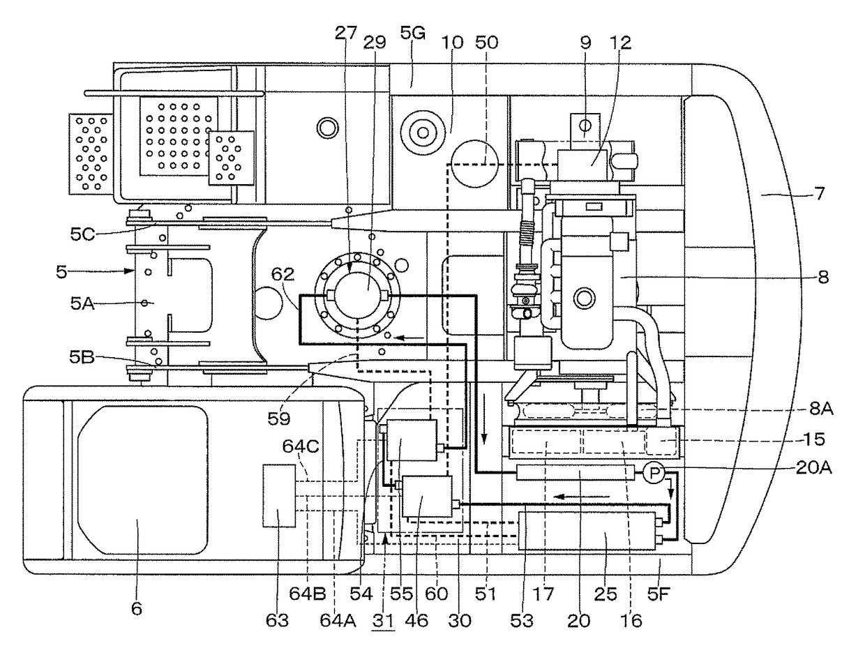
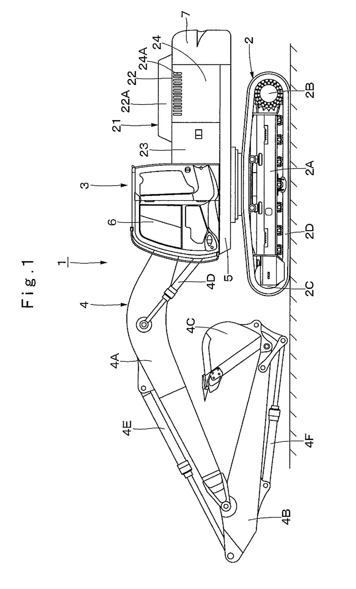
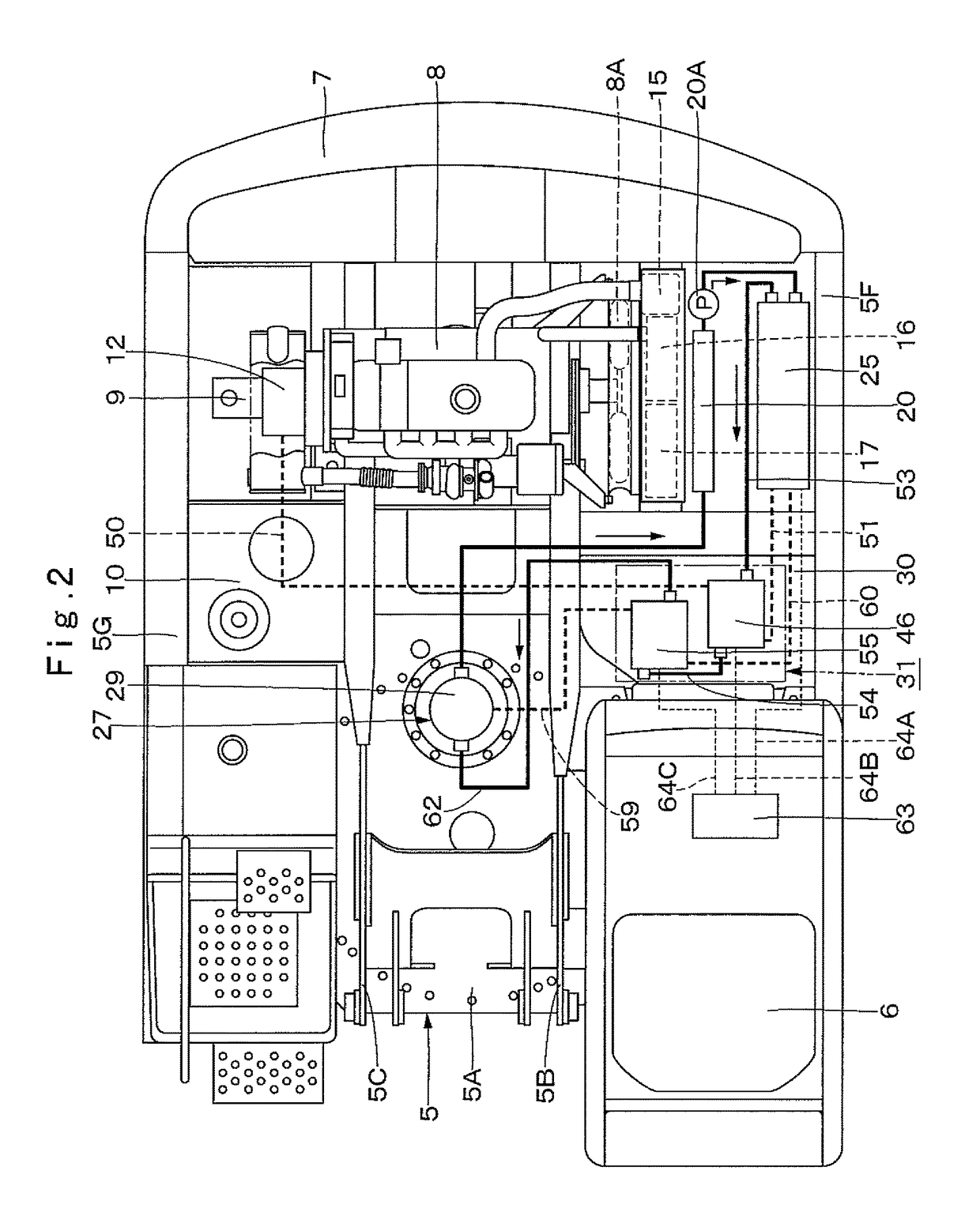
[0023]FIG. 1 to FIG. 10 show a hybrid-type working machine according to the present invention. In FIG. 1, indicated at 1 is a hybrid-type hydraulic excavator as a representative example of hybrid-type working machines. A vehicle body of the hydraulic excavator 1 comprises an automotive lower traveling structure 2 of a crawler type and an upper revolving structure 3 that is mounted on the lower traveling structure 2 to be capable of revolving thereon. A working mechanism 4 is provided in the front side of the upper revolving structure 3 to be capable of lifting and tilting thereto, and the hydraulic excavator 1 can perform an excavating operation of earth and sand and the like by using the working mechanism 4.

[0024]The lower traveling structure 2 comprises a track frame having left and right side frames 2A (the left side only is shown), a drive wheel 2B provided on one side of each of the side frames 2A in the front-rear direction (length direction), an idler wheel 2C provided on the...

second embodiment

[0129]The aforementioned second embodiment is explained by taking a case where the first inverter 46 is mounted on the upper surface 71A1 side of the upper side mounting member 71 and the second inverter 72 is mounted on the lower surface 71A2 side of the upper side mounting member 71, as an example. However, the present invention is not limited thereto, but, for example, the second inverter 72 may be mounted on the upper surface 71A1 side of the upper side mounting member 71 and the first inverter 46 may be mounted on the lower surface 71A2 side of the upper side mounting member 71.

[0130]The aforementioned second embodiment is explained by taking a case where the upper side mounting member 71 is mounted on the lower side mounting member 38, as an example. However, the present invention is not limited thereto, but, for example, the upper side mounting member 71 may be mounted directly on the left and right vibration isolating members 35 without using the lower side mounting member 3...


PUM


Abstract

An assist generator motor is driven by an engine to generate power or assists in a drive of the engine by supply of power from an electricity storage device. A revolving electric motor is driven by power supplied from the electricity storage device or supplies regeneration power generated by a regeneration operation to the electricity storage device. The assist generator motor is controlled by a first inverter. The revolving electric motor is controlled by a second inverter. The first inverter and the second inverter are mounted on a support bracket elastically supported on a revolving frame in a position different from a position where the electricity storage device is mounted.

Description

TECHNICAL FIELD[0001]The present invention relates to working machines such as hydraulic excavators and wheel-type hydraulic excavators and the like, and particularly to a hybrid-type working machine using both an engine and an electric machinery (electric motor) together as a power source.BACKGROUND ART[0002]In general, a hydraulic excavator as a representative example of a working machine used at a construction site and the like, is provided with a vehicle body comprising an automotive lower traveling structure and an upper revolving structure that is mounted on the lower traveling structure to be able to revolve thereon. A working mechanism for performing an operation such as an excavating operation and the like is mounted on the front side of the upper revolving structure.[0003]On the other hand, there is known a hybrid-type working machine using both an engine and an electric motor together, as a working machine such as a hydraulic excavator and the like. This hybrid-type worki...

Claims


Application Information

Patent Timeline
Patent Type & Authority Patents(United States)
IPC IPC(8): E02F9/20B60K6/485E02F9/08E02F9/12E02F3/32
CPCE02F9/2075B60K6/485E02F9/0858E02F9/0866E02F9/123E02F9/2091E02F9/2095B60Y2200/412E02F3/32Y10S903/903B60K1/00B60K2001/003B60L2210/40B60W2300/17Y02T10/62Y02T10/72
Inventor OTA, YASUNORIOJIMA, MITSUGUEGAWA, SHUJIAZUMA, YUJI
Owner NIHON KENKI CO LTD
Why Eureka
Try Eureka