Supercharge Your Innovation With Domain-Expert AI Agents!

Hose reel assembly

a technology of hose reels and assembly parts, applied in the field of reels, can solve the problems of increasing the size of the reel assembly, reducing the service life of the reel, and requiring frequent replacement,

Active Publication Date: 2020-03-17
GREAT STUFF INC
View PDF22 Cites 0 Cited by
  • Summary
  • Abstract
  • Description
  • Claims
  • Application Information

AI Technical Summary

Benefits of technology

The solution provides a durable, efficient, and user-friendly hose reel assembly with reduced part count, improved spooling efficiency, and extended component lifespan by minimizing exposure to environmental factors and optimizing motor usage.

Problems solved by technology

However, such reversing screws tend to wear out quickly, degrading reel performance and necessitating frequent replacement.
Further, such reversing screws are bulky and increase the size of the reel assembly.
Unfortunately, the repeated reversing of the motor increases the spooling time and causes the motor to wear down sooner.
Over time, such moving parts can become damaged due to exposure.
Such exposure can cause the moving parts of the reel to wear more rapidly, resulting in reduced performance quality.
Additionally, many reel constructions include additional parts outside the reel assembly, which increases the number of steps that the user has to take to use the reel or the number of parts the user must interconnect to use the reel, which increases the complexity of using the reel and is inconvenient for the user.

Method used


Image

  • Hose reel assembly
  • Hose reel assembly
  • Hose reel assembly

Examples


Embodiment Construction

[0044]In the following detailed description, terms of orientation such as “top,”“bottom,”“upper,”“lower,”“front,”“rear,” and “end” are used herein to simplify the description of the context of the illustrated embodiments. Likewise, terms of sequence, such as “first” and “second,” are used to simplify the description of the illustrated embodiments. Because other orientations and sequences are possible, however, the present invention should not be limited to the illustrated orientation. Those skilled in the art will appreciate that other orientations of the various components described above are possible.

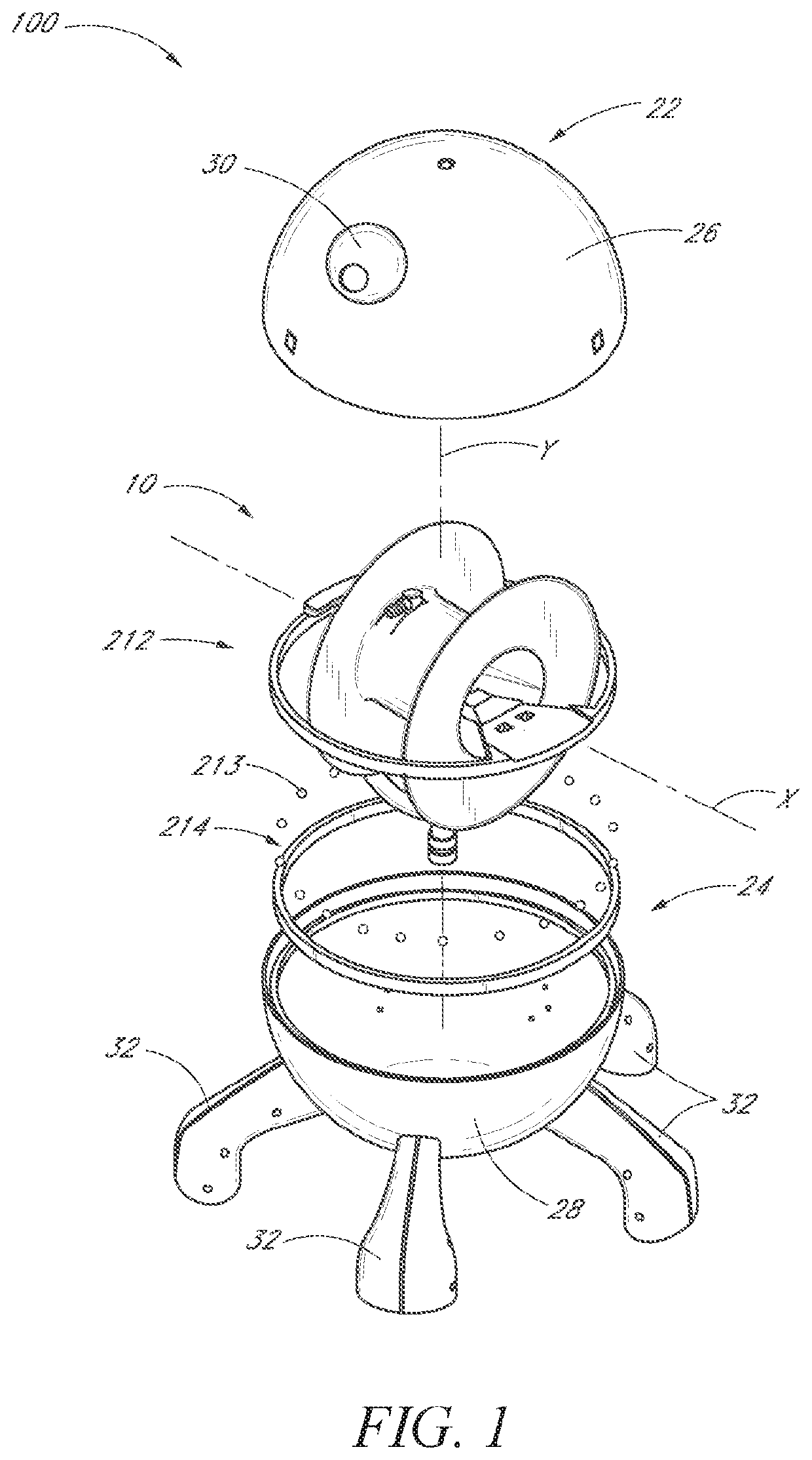
[0045]FIG. 1 illustrates one embodiment of a reel assembly 100 substantially enclosing a drum assembly 10 in a housing. In the illustrated embodiment, the housing includes an upper or top shell portion 22 and a lower or bottom shell portion 24. Additionally, the upper and lower shell portions 22, 24 have the shape of upper and lower domes 26, 28, respectively, so that the reel assembl...


PUM


Abstract

A hose reel assembly can include a hose reel rotatable about a reel axis, and a first portion of linear material having a first proximal end portion and a first distal end portion, the first distal end portion configured to dispense a fluid. The hose reel assembly can include a second portion of linear material having a second proximal end portion connected to the hose reel and a second distal end portion. A connector can removably attach the second distal end portion of the second portion of linear material with the first proximal end portion of the first portion of linear material. A strain relief member can be configured to control an amount by which the second portion of linear material unspools from the hose reel.

Description

CROSS-REFERENCE TO RELATED APPLICATIONS[0001]This application claims priority to U.S. Provisional Patent Application No. 62 / 151,638, filed Apr. 23, 2015, the contents of which are incorporated by reference herein in their entirety and for all purposes.BACKGROUND[0002]Field[0003]The field relates generally to reels for spooling linear material and, in particular, to a reel including a connector for removably attaching two portions of linear material.[0004]Description of the Related Art[0005]Reels for spooling linear material, such as a hose or wire, onto a rotating drum have incorporated reciprocating motion of a guide through which the linear material passes, to advantageously cause the linear material to be wrapped substantially uniformly around most of the surface area of the drum.[0006]Several methods have been utilized in the past for achieving such reciprocating motion. One common approach is to use a rotating reversing screw which causes a guide to translate back and forth in ...

Claims


Application Information

Patent Timeline
Patent Type & Authority Patents(United States)
IPC IPC(8): B65H75/44B65H75/40
CPCB65H75/4471B65H75/403B65H75/4428B65H75/4478B65H75/4407B65H2701/33
Inventor TRACEY, JAMES B. A.
Owner GREAT STUFF INC
Features
  • R&D
  • Intellectual Property
  • Life Sciences
  • Materials
  • Tech Scout
  • Unparalleled Data Quality
  • Higher Quality Content
  • 60% Fewer Hallucinations
Learn More