Spacer assembly

a technology of spacers and assembly parts, applied in the direction of fastening means, dismountable cabinets, rod connections, etc., can solve the problems of not being easily removable or replaced, and the installation of moldings or facing strips is typically permanent, so as to achieve convenient disassembly, easy installation, and sufficient structural support

Active Publication Date: 2020-06-23
NEWAGE PROD
View PDF19 Cites 0 Cited by
  • Summary
  • Abstract
  • Description
  • Claims
  • Application Information

AI Technical Summary

Benefits of technology

[0008]The spacer assembly of the present invention provides sufficient structural support and a desirable aesthetic appearance for forming cabinet assemblies from cabinet subassemblies. The spacer assembly is easy to install, and easy to disassemble after installation, thus allowing cabinet subassemblies to be arranged, and rearranged, in a wide variety of different ways as desired.

Problems solved by technology

These moldings or facing strips are typically permanently installed and are not readily removable or replaceable.

Method used


Image

  • Spacer assembly
  • Spacer assembly
  • Spacer assembly

Examples


Embodiment Construction

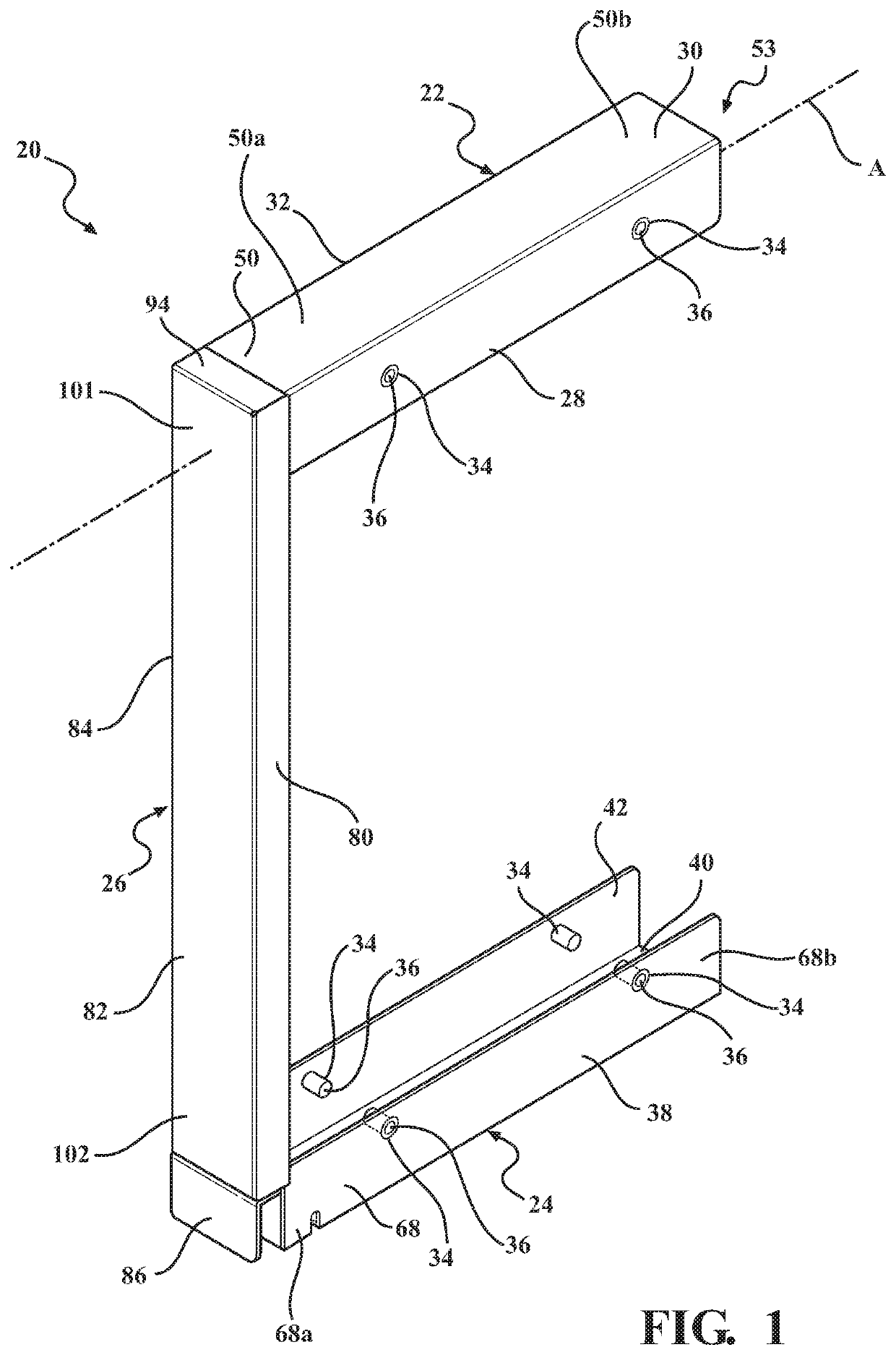
[0031]Referring now to the figures, wherein like numerals indicate like or corresponding parts, a spacer assembly 20 is generally shown in FIGS. 1-4 and 7-18. Generally, the spacer assembly 20 includes a first frame member 22 extending along a longitudinal axis A and a second frame member 24 extending parallel to the longitudinal axis A. The spacer assembly 20 additionally includes a decorative cover 26, extending normal to the longitudinal axis A mounted to the first frame member 22, and fastened to the second frame member 24.

[0032]The longitudinal axis A, as described herein, is not intended to describe an axis that is generally parallel to or along the lines of longitude associated with describing map coordinates of the earth that extend between the north and south pole, but is intended to generally describe the longest lengthwise direction of the part described (here the first frame member 22. Accordingly, further descriptions of the longitudinal axis A of other components are d...


PUM


Abstract

A spacer assembly for use in supporting and securing a first cabinet subassembly to a second cabinet subassembly to form a cabinet assembly includes a first frame member, a second frame member and a decorative cover. The first frame member extends between a top attachment end and a top non-attachment end and includes a mount having an indented ledge coupled at the top attachment end. The second frame member extends between a bottom attachment end and a bottom non-attachment end and includes a bottom plate extending from the bottom attachment end and a flange extending outwardly away from the bottom plate. The decorative cover is coupled onto the mount of the first frame member and onto the flange of the second frame member.

Description

CROSS-REFERENCE TO RELATED APPLICATIONS[0001]The present invention claims priority to U.S. Provisional Application No. 62 / 485,639, filed Apr. 14, 2017, the contents of which are hereby incorporated by reference.FIELD OF THE DISCLOSURE[0002]The present invention relates, generally, to a spacer assembly for supporting and securing a first cabinet assembly to a second cabinet assembly and for providing an aesthetically pleasing decorative cover therebetween.DESCRIPTION OF RELATED ART[0003]It is also well known to attach individual storage cabinets (i.e., cabinet subassemblies) together along their side walls where cabinet assemblies having additional storage capabilities is desired. Typically, the cabinet subassemblies are coupled together by bringing their sidewalls into an abutting relationship and inserting fastening devices, such as screws or bolts, through the side walls. The resultant cabinet assembly thus include a seam corresponding to the juncture of the cabinet subassemblies ...

Claims


Application Information

Patent Timeline
Patent Type & Authority Patents(United States)
IPC IPC(8): A47B87/00A47B95/04
CPCA47B95/04A47B87/008A47B47/00A47B87/00A47B96/04A47B97/00F16B7/00F16B7/187
Inventor HARDER, MITCHVANDENHAM, ROBERT
Owner NEWAGE PROD
Why Eureka
Try Eureka