
Interbody fusion cages

a technology of interbody fusion and cage, which is applied in the field of spinal implants, can solve the problems of reducing the options for interbody graft use to enhance fixation and fusion, and achieve the effects of enhancing fixation and fusion, facilitating transforaminal insertion, and sufficient structural suppor

Active Publication Date: 2021-03-23
MOBARN MEDICAL DEVICES LLC
View PDF5 Cites 0 Cited by
  • Summary
  • Abstract
  • Description
  • Claims
  • Application Information

AI Technical Summary

Benefits of technology

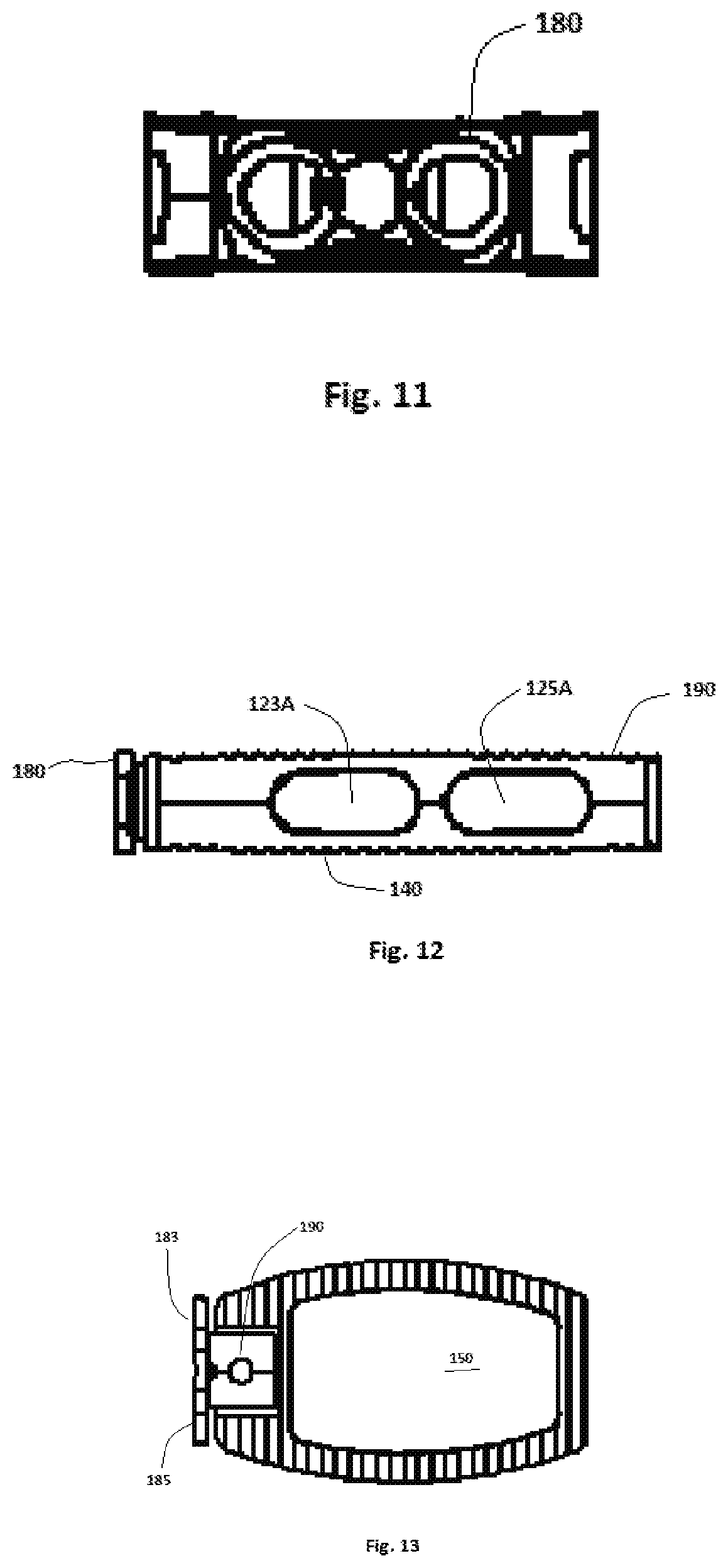
[0006]It is an object of the inventions to provide LIF cages that provide sufficient structural support for LIF procedures while also featuring large internal void volumes communicating with large external openings, the larger volumes and openings relative to structure providing increased options for using interbody graft to enhance fixation and fusion.
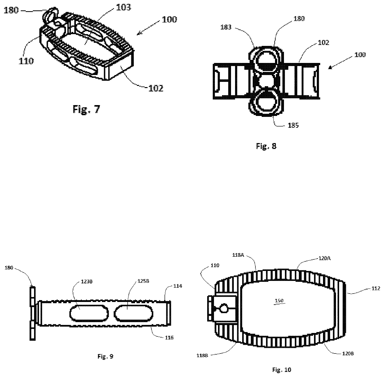
[0007]One object of the inventions is to provide a TUT cage that can be readily inserted transforaminally and which provides a large void volume and external openings for use with interbody graft.
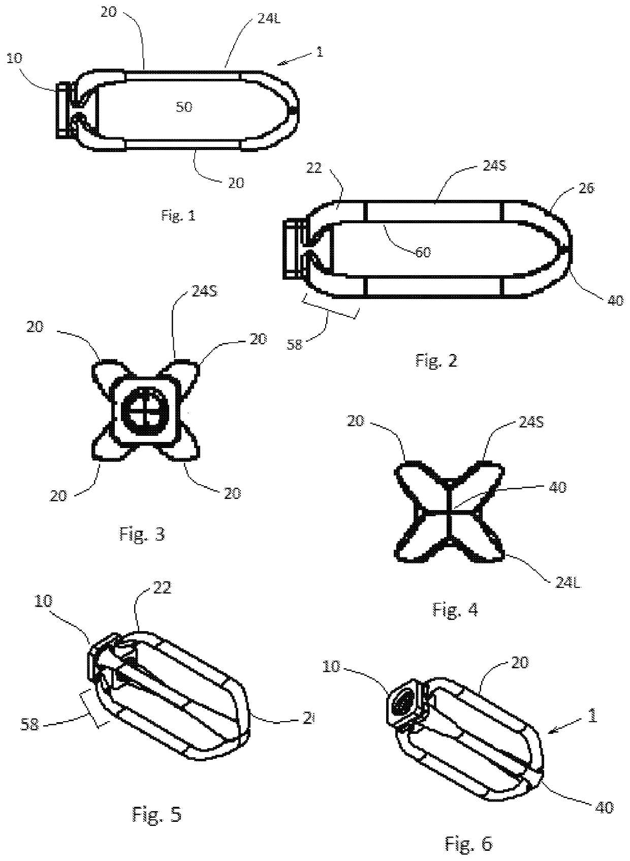
[0012]Embodiments of the invention include an implant device for interbody fusion of lumbar or cervical vertebrae comprising a unibody cage structure having an enveloping cage volume and a minimized material volume. The cage structure comprises a first and a second generally planar ring member, each ring member formed from an opposing pair of lengthwise joists and an opposing pair of cross joists, the joists together forming a large opening through the ring member. The ring members are fixedly sandwiched on a plurality of support members, the support members holding the ring members in a spaced apart relationship to thereby provide a large void volume relative to the enveloping cage volume, to thereby allow for receipt of a large volume of bone graft within the cage structure.
[0014]In embodiments, the ring members are positioned on opposing lateral sides of the cage, such that one of the lengthwise joists of each ring member serves as a superior loading surface, the other of the lengthwise joists of each ring member serves as an inferior loading surface, and the cross joists are configured to distribute load between opposing lengthwise joists. The cross joists may be curved, such that each ring member has a substantially race-track configuration. The cage may further comprise at least one substantially vertical strut sandwiched between the opposing lengthwise joists of each ring member to further distribute load. The at least one substantially vertical strut may comprise a pair of substantially vertical struts.
[0019]In embodiments, the device is sized and configured for use as an anterior lumbar interbody fusion (ALIF) cage. In ALIF embodiments, the ratio of the void volume to the enveloping cage volume may be between about 0.83 to about 0.85. A ratio of the void volume to the material volume may be between about 5.1 to about 5.2. The may be about 4 mm wide and about 1.5 mm thick. The vertical struts may have an outer diameter of about 4 mm. A clip-on side cap member may be provided, the side cap member configured to removably attach to the vertical strut members to thereby assist in containing bone graft within the cage.

Problems solved by technology

Current LIF and ACDF cages emphasize structural support over openness, which decreases options for the use of interbody graft to enhance fixation and fusion.

Method used


Image

  • Interbody fusion cages
  • Interbody fusion cages
  • Interbody fusion cages

Examples


Embodiment Construction

[0062]In the following detailed description of the preferred embodiments, reference is made to the accompanying drawings which form a part hereof, and in which are shown by way of illustration specific embodiments in which the invention may be practiced. It is to be understood that other embodiments may be utilized and structural changes may be made without departing from the scope of the present invention.

[0063]The inventions will be defined partly with respect to certain volumes and ratios. As used for the various cage embodiments described herein, “enveloping volume” means the volume of a rectangular box tightly surrounding the outermost edges of the cage. “Net enveloping volume” means “enveloping volume” minus the triangular wedge area that is not occupied by the cage due to the presence of a lordosis angle (one side higher than the other). As such, enveloping volume has a slightly large volume than net enveloping volume. “Material volume” (sometimes referred to as “structural v...


PUM

PropertyMeasurementUnit
diameteraaaaaaaaaa
outer diameteraaaaaaaaaa
lordosis angleaaaaaaaaaa

Abstract

An implant for interbody fusion of vertebrae comprising a unibody cage structure having an enveloping cage volume and a minimized material volume. The cage structure comprises a first and a second generally planar ring member, each ring member formed from an opposing pair of lengthwise joists and an opposing pair of cross joists, the joists together forming a large opening through the ring member. The ring members are fixedly sandwiched on a plurality of support members, the support members holding the ring members in a spaced apart relationship to thereby provide a large void volume relative to the enveloping cage volume, to thereby allow for receipt of a large volume of bone graft within the cage structure.

Description

CROSS REFERENCE TO RELATED APPLICATIONS[0001]This application is a 35 USC § 371 of PCT / US2017 / 034883 filed May 27, 2017, which is pending; PCT / US2017 / 034883 claims priority to U.S. Provisional Patent Application 62 / 342,572, filed May 27, 2016. This application claims the benefit of and incorporates by reference all of the above cited applications.STATEMENT REGARDING FEDERALLY SPONSORED RESEARCH[0002]Not applicableFIELD OF THE INVENTION[0003]The present invention relates to spinal implants, and more particularly to lumbar and anterior cervical discectomy fusion cages configured to receive bone graft.BACKGROUND OF THE INVENTION[0004]Various implants have been developed for use in lumbar interbody fusion (LIF) and anterior cervical discectomy fusion (ACDF), including cages. Current LIF and ACDF cages emphasize structural support over openness, which decreases options for the use of interbody graft to enhance fixation and fusion. There is a need for interbody fusion cages that overcome ...

Claims


Application Information

Patent Timeline
Patent Type & Authority Patents(United States)
IPC IPC(8): A61F2/44A61F2/30A61F2/28
CPCA61F2/4465A61F2/28A61F2/2846A61F2/30744A61F2/4455A61F2002/305A61F2002/3093A61F2002/30179A61F2002/30405A61F2002/30578A61F2002/30593A61F2002/30904A61F2310/00023A61F2310/00029A61F2310/00359A61F2310/00407A61F2310/00413A61F2/4601A61F2002/302
Inventor FREUDENBERGER, CURT
Owner MOBARN MEDICAL DEVICES LLC
Learn More