Charging device and control method thereof

a charging device and control method technology, applied in the direction of electric variable regulation, process and machine control, instruments, etc., can solve the problems of insufficient electric energy provided by the adapter, insufficient electric energy for the electric device, and certain problems of the traditional charging devi

Active Publication Date: 2020-09-08
ANPEC ELECTRONICS CORPORATION
View PDF6 Cites 1 Cited by
  • Summary
  • Abstract
  • Description
  • Claims
  • Application Information

AI Technical Summary

Benefits of technology

[0011]To sum up, when the load of an electronic device is a heavy load, the charging device and the control method thereof provided by the present disclosure can maintain the input current provided by the adapter at a safe current level, and helps the adaptor via the energy storage unit provide electric energy to the electronic device. Thereby, the adapter will not be damaged by a high output power thereof. Moreover, the charging device and the control method thereof provided by the present disclosure can dynamically adjust the second charging current provided by the energy storage unit, and can directly detect the second charging current to determine whether to end the boost mode of the charging module. Compared with an energy storage unit of a traditional charging device that can only provide a constant current, the charging device and the control method thereof provided by the present disclosure will not make the charging device work in a wrong mode due to variation or sudden change of the input voltage provided by the adapter.

Problems solved by technology

Usually, the portable electric devices consume power quickly, so the users are used to keeping a charging device, such as a power bank, at hand to charge their portable electric devices if necessary.
If the maximum of the current is, for example, 1 A but an electric device to be charged needs a 1.5 A current, and the electric energy provided by the adapter is apparently insufficient for the electric device.
However, the traditional charging device has certain problems.
The current provided by the adapter decreases, so the traditional charging device wrongly detects that the electric energy provided by the adapter is sufficient for the electric energy needed by the electric device, and turns to enable the buck converter and starts to charge the battery.
Nevertheless, the adapter cannot provide a sufficient electric energy to the electronic device, and eventually the traditional charging device will again turn to enable the boost converter so that the battery can provide part of electric energy that the electric device needs.
Briefly, the traditional charging device keeps changing its working mode (for example, from the buck converter to the boost converter, or from the boost converter to the buck converter), and thus is unable to provide electric energy to the electric device stably.
Additionally, another problem that the traditional charging device is that, there is a period of time needed for the traditional charging device to wait for its processor to determine what kind of control signal should be sent to change its working mode (for example, from the buck mode to the boost mode, or from the boost mode to the buck mode).
Thus, the traditional charging device may not be able to immediately provide electric energy to an electronic device.

Method used


Image

  • Charging device and control method thereof
  • Charging device and control method thereof
  • Charging device and control method thereof

Examples


first embodiment

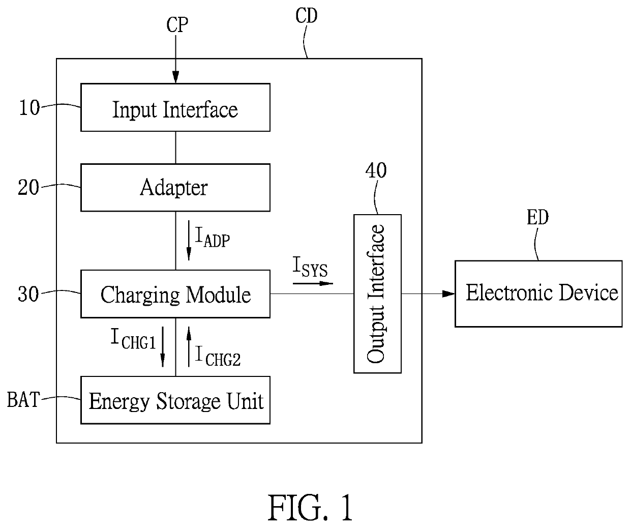
[0023]Reference is made to FIG. 1, which is a block diagram of a charging device of the present disclosure. The charging device CD can be, for example, a power bank, which is an OTG device. Briefly, the charging device CD can receive and convert commercial power CP into another form of electric energy and store the electric energy. The charging device CD can also provide the stored electric energy to other electric devices. The charging device CD includes at least one input interface 10, an adapter 20, a charging module 30, an energy storage unit BAT and at least one output interface 40. The adapter 20 is connected to the input interface 10 and the charging module 30. The charging module 30 is connected to the energy storage unit BAT and the output interface 40. In addition, an electronic device ED is connected to the output interface 40.

[0024]The electronic device ED can be, for example, a mobile phone, a tablet, a music player or a video player having a USB interface, but it is no...

second embodiment

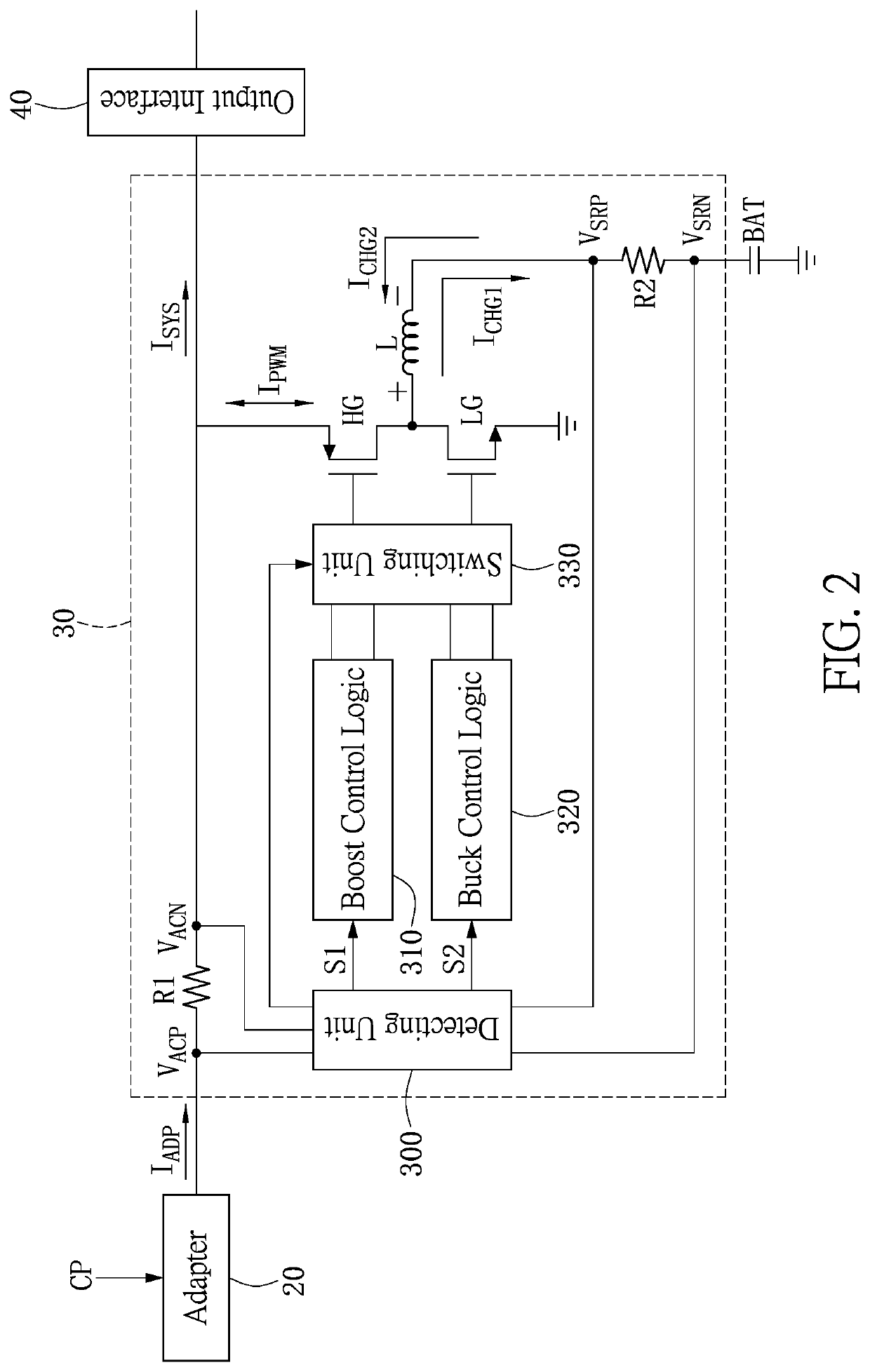
[0061]Reference is made to FIG. 4, which is a circuit layout diagram of a charging device of the present disclosure. As shown in FIG. 4, the charging device includes the adapter 20, the energy storage unit BAT and the charging module 30. The charging module 30 is connected to the adapter 20, the energy storage unit BAT and the electronic device.

[0062]The charging module 30 receives the adapter current from the adapter 20 and the second charging current ICHG2 from the charging module 30. The charging module 30 provides the first charging current ICHG1 to the energy storage unit BAT and an output current ISYS to the electronic device connected to a system terminal at which a voltage VSYS is provided.

[0063]The charging module 30 includes the detecting unit 300, the boost control logic 310, the buck control logic 320, the switching unit 330, the upper bridge switch HG and the lower bridge switch LG.

[0064]The detecting unit 300 includes a first current sense amplifier CSA1, a first error...


PUM


Abstract

A charging device and a control method thereof are provided. The charging device includes an adapter, an energy storage unit and a charging module. The adapter provides an adapter current. The charging module receives the adapter current and provides a first charging current to charge the energy storage unit, or an output current to charge an electronic device. When the input current is larger than a first preset current and the first charging current is equal to or less than a third preset current, the charging module operates in a boost mode, such that the energy storage unit provides a second charging current to the charging module. When the second charging current is larger than the third preset current, the charging module enters a buck mode such that the energy storage unit is charged by the first charging current.

Description

CROSS-REFERENCE TO RELATED PATENT APPLICATION[0001]This application is a continuation-in-part application of and claims the priority benefit of a prior application Ser. No. 15 / 198,446, filed on Jun. 30, 2016, now pending, which claims the priority benefits of Taiwan application serial no. 105109451, filed on Mar. 25, 2016. The entirety of each of the above patent applications is hereby incorporated by reference herein and made a part of this specification.BACKGROUND OF THE INVENTION1. Field of the Invention[0002]The present disclosure relates to a charging device; in particular, to a charging device that can provide an electric energy safely and effectively.2. Description of Related Art[0003]With the development of technology, portable electric devices have become essential in people's lives, such as the mobile phone, the tablet, the music player, the video player or the like that have an USB interface.[0004]Usually, the portable electric devices consume power quickly, so the users ...

Claims


Application Information

Patent Timeline
Patent Type & Authority Patents(United States)
IPC IPC(8): H02J7/00H02M3/158
CPCH02J7/00H02M3/1582H02M3/158H02J7/00712H02J2207/20H02J7/00714
Inventor CHEN, CHIH-NINGSU, CHIH-HENG
Owner ANPEC ELECTRONICS CORPORATION
Why Eureka
Try Eureka