Automatic magnetic buckle and its use method
a technology of automatic buckles and buckles, applied in the field of buckle structures, can solve the problems of buckle base and clamping head not being firm enough, buckle base and clamping head not being connected and disconnected, and inconvenient us
- Summary
- Abstract
- Description
- Claims
- Application Information
AI Technical Summary
Benefits of technology
Problems solved by technology
Method used
Image

Examples
embodiment 1
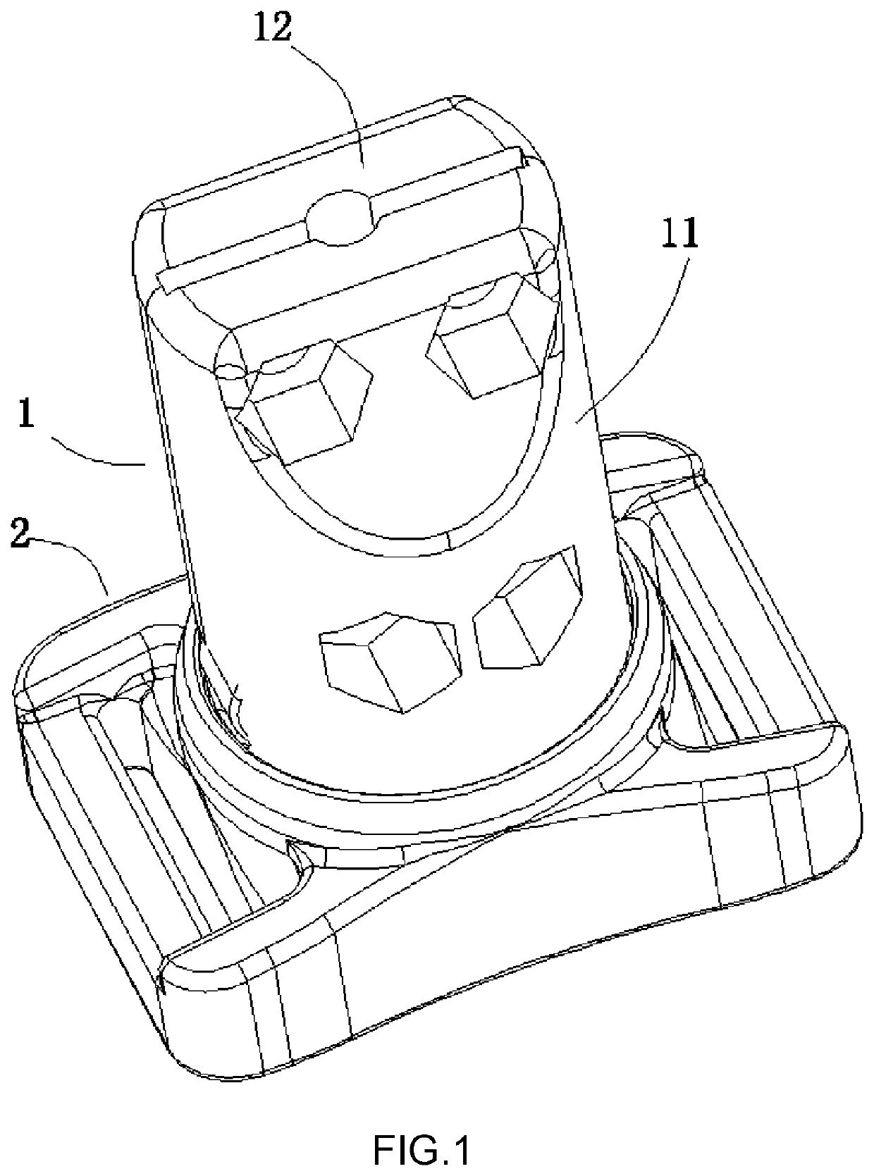
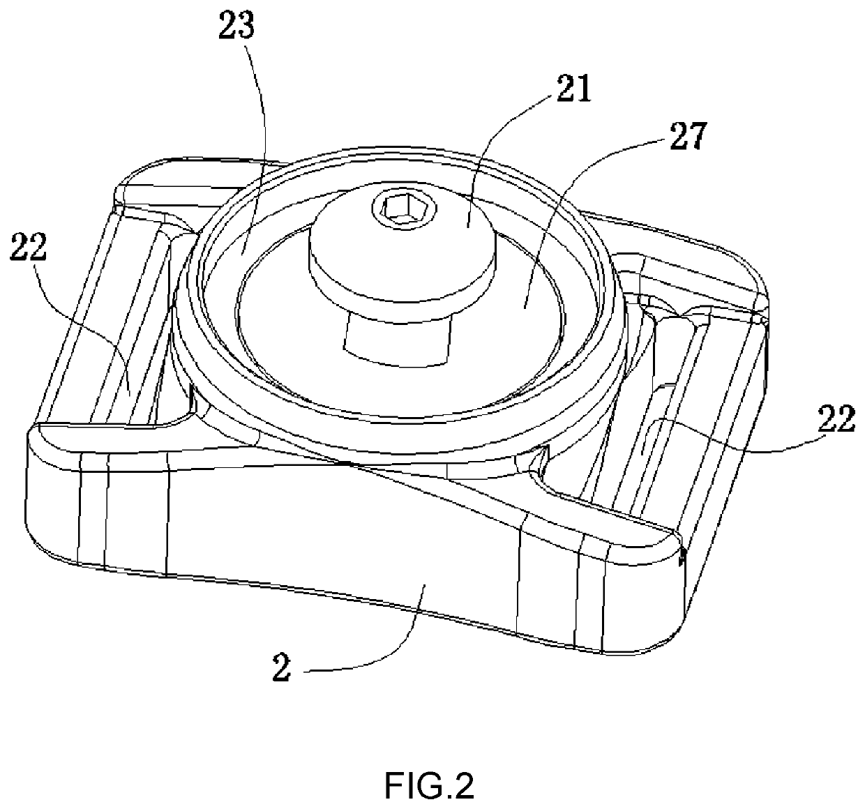
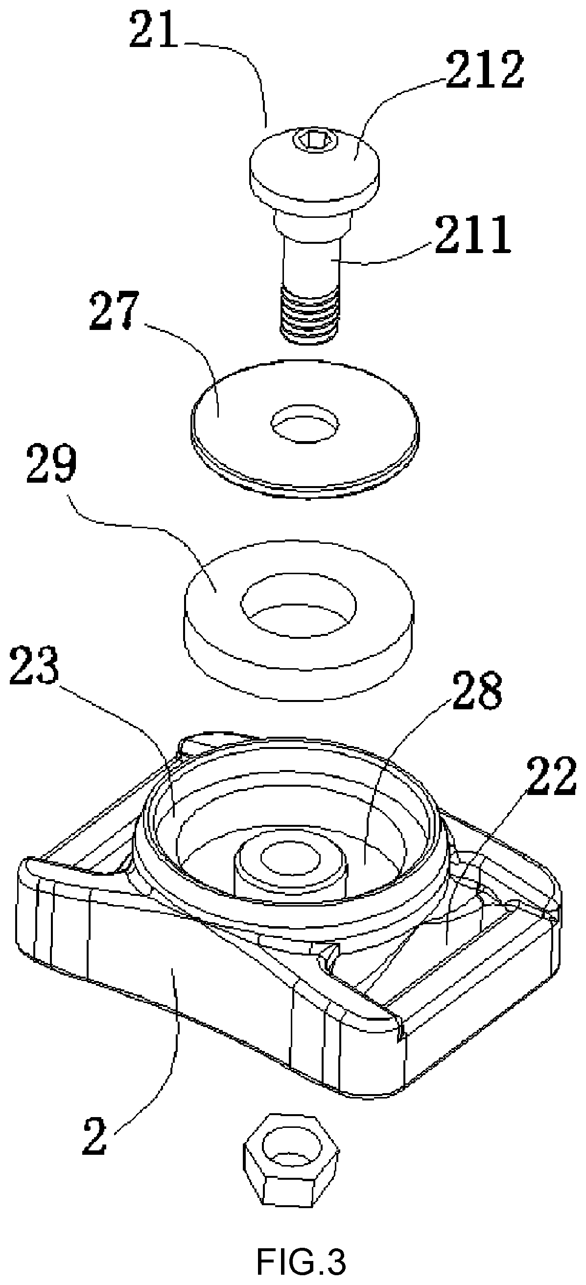
[0040]Refer to FIG. 1 to FIG. 6 and FIG. 9 for An automatic magnetic buckle provided by the present embodiment comprises a matching clamping head 1 and a buckle base 2. The said clamping head 1 comprises a clamping head housing, and the said clamping head housing has a cavity extending through the upper and lower ends of the clamping head housing. The said cavity is set with a buckle subassembly, and the said buckle base 2 is set with a buckle head 21 matching with the said buckle subassembly, and the said clamping head 1 and the buckle base 2 are set with magnetic subassemblies which are mutually attracted. Clamping head 1 and buckle base 2 are attracted together through the matching of the magnetic subassembly. The buckle subassembly is matched with the buckle head 21 to securely connect the clamping head 1 and the buckle base 2.
[0041]As shown in FIG. 4 and FIG. 5, the said buckle subassembly comprises a left fastener 13 and a right fastener 14 which are symmetrically set in the ...
embodiment 3
[0063]Refer to FIG. 12 to FIG. 15 for The present embodiment is substantially the same as Embodiments 1 and 2, but their differences are as follows: the said fastener unfolding device has two pressing members 9, and the said pressing members include a pressing rod 91 and a pressing head 92 which are interconnected. The pressing rods 91 of the two pressing members 9 are respectively in contact with the outer sides of the left fastener 13 and the right fastener 14, and the said pressing head 92 stretches out the outer periphery of the clamping head housing.
[0064]The said clamping head housing includes a front housing 11 and a rear housing 12, and the opposite walls of the front housing 11 and the rear housing 12 are respectively set with a half recess 16 forming the said cavity.
[0065]The opposite walls of the front housing 11 and the rear housing 12 are respectively relative to the pressing rod 91 and the pressing head 92, forming a holding tank 10.
PUM
 Abstract
Description
Claims
Application Information
 - R&D Engineer
- R&D Manager
- IP Professional
- Industry Leading Data Capabilities
- Powerful AI technology
- Patent DNA Extraction
Browse by: Latest US Patents, China's latest patents, Technical Efficacy Thesaurus, Application Domain, Technology Topic.
© 2024 PatSnap. All rights reserved.Legal|Privacy policy|Modern Slavery Act Transparency Statement|Sitemap