Check patentability & draft patents in minutes with Patsnap Eureka AI!

Fuel cell system and control method thereof

a fuel cell and control method technology, applied in the direction of fuel cell control, fuel cell, electric generators, etc., can solve the problem of insufficient accurate estimation of the state inside the fuel cell, and achieve the effect of accurate estimation of the water amount and reduction of the amount of water

Active Publication Date: 2020-10-20
TOYOTA JIDOSHA KK
View PDF5 Cites 0 Cited by
  • Summary
  • Abstract
  • Description
  • Claims
  • Application Information

AI Technical Summary

Benefits of technology

Enables accurate estimation and management of water amounts on the anode side, improving fuel cell efficiency by preventing water accumulation and maintaining optimal reaction conditions, thereby enhancing power generation performance.

Problems solved by technology

However, the water amount inside the fuel cell estimated in JP 2015-099727 A is a water amount combining a water amount on an anode side and a water amount on a cathode side, and is therefore inadequate for accurately estimating the state inside the fuel cell.

Method used


Image

  • Fuel cell system and control method thereof
  • Fuel cell system and control method thereof
  • Fuel cell system and control method thereof

Examples


first embodiment

A. First Embodiment

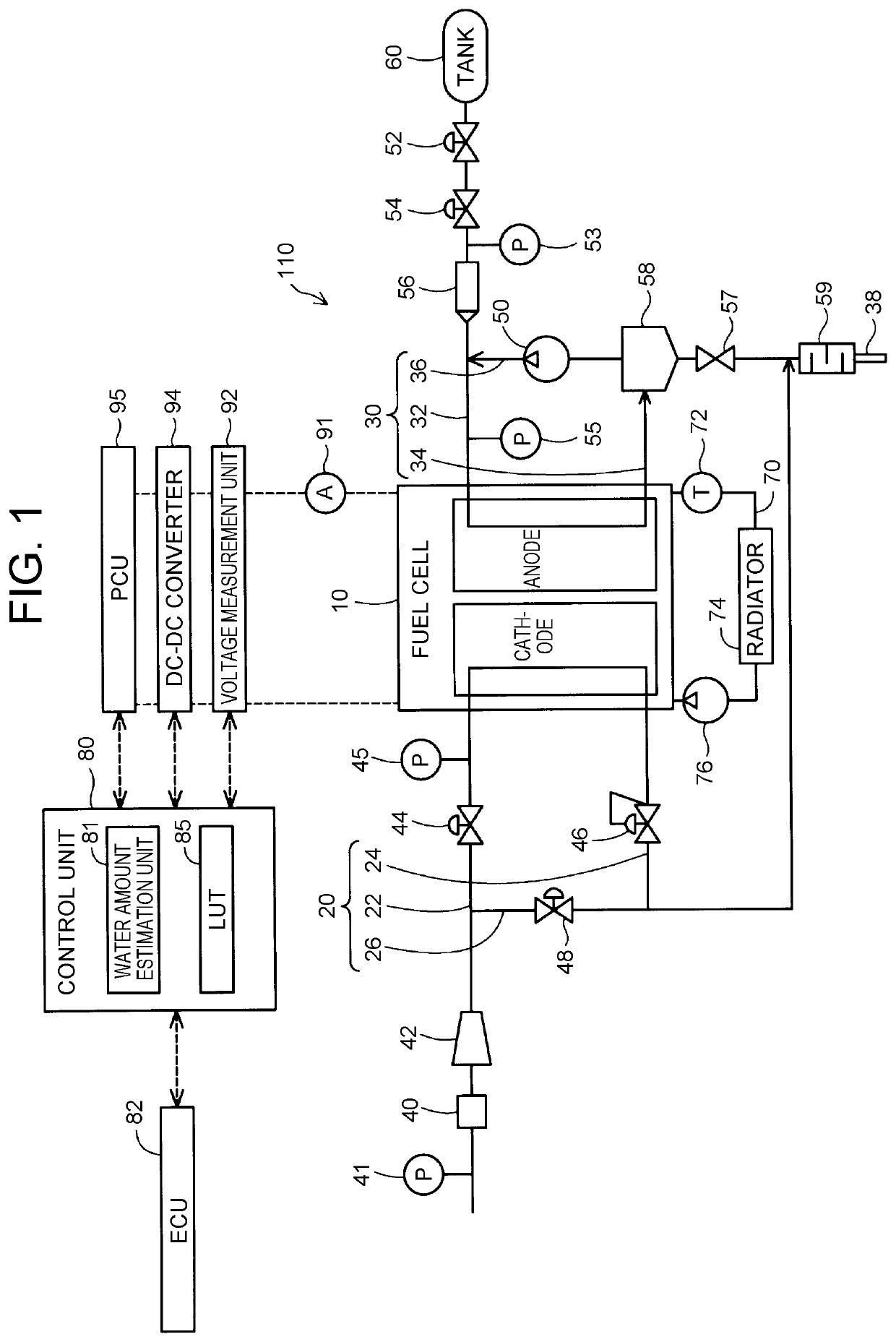
[0017]FIG. 1 is a diagram showing the configuration of a fuel cell system 110 that is an embodiment of the present disclosure. The fuel cell system 110 includes a fuel cell stack (hereinafter referred to simply as a “fuel cell”) 10, a cathode gas passage 20, an anode gas passage 30, a cooling passage 70, and a control unit 80. In this embodiment, the fuel cell system 110 is installed in a vehicle.

[0018]For example, the fuel cell 10 is formed by stacking power generation modules each including a membrane electrode assembly (MEA) that is an electrolyte membrane with an anode electrode and a cathode electrode respectively joined to both sides. The fuel cell 10 generates electricity by an electrochemical reaction between a hydrogen gas as an anode gas that is supplied from an anode gas tank 60 and oxygen as a cathode gas that is present in the atmosphere. Instead of a hydrogen gas, for example, alcohol or hydrocarbon may be used as the anode gas.

[0019]The cathode gas ...

second embodiment

B. Second Embodiment

[0046]FIG. 6 is a diagram showing the configuration of a fuel cell system 110A in a second embodiment. FIG. 7 is a flowchart in the second embodiment. The second embodiment is different from the first embodiment in that step P135 is further performed after step P130 and that a reduction control unit 83 that performs reduction control, to be described later, is included in the control unit 80, but is otherwise the same as the first embodiment.

[0047]In the second embodiment, when the control unit 80 estimates that the water amount on the anode side of the fuel cell 10 is larger than the water amount threshold value Th (step P130), the control unit 80 performs the reduction control of reducing the water amount on the anode side of the fuel cell 10 (step P135). In this embodiment, the control unit 80 performs, as the reduction control, control of increasing the rotation speed of the pump 50 compared with that when the reduction control is not performed. Thus, water i...


PUM

PropertyMeasurementUnit
unit timeaaaaaaaaaa
timeaaaaaaaaaa
timeaaaaaaaaaa

Abstract

Provided is a fuel cell system including: a pressure measurement unit that acquires a measured pressure value of an anode gas at an anode gas inlet or an anode gas outlet of a fuel cell; and a water amount estimation unit. The water amount estimation unit obtains, from a plurality of circumstantial parameters including an open time of an injector provided in the anode gas supply passage and the measured pressure value measured before the injector is opened, an assumed pressure rise that is assumed based on the water amount being equal to the water amount threshold value. When a measured pressure rise of the measured pressure value resulting from opening the injector is larger than the assumed pressure rise, the water amount estimation unit estimates that the water amount is larger than the water amount threshold value.

Description

INCORPORATION BY REFERENCE[0001]The disclosure of Japanese Patent Application No. 2018-028927 filed on Feb. 21, 2018 including the specification, drawings and abstract is incorporated herein by reference in its entirety.BACKGROUND1. Technical Field[0002]The present disclosure relates to a fuel cell system and a control method thereof.2. Description of Related Art[0003]Japanese Patent Application Publication No. 2015-099727 (JP 2015-099727 A) discloses a method of estimating a water amount inside a fuel cell by using an impedance of the fuel cell.SUMMARY[0004]However, the water amount inside the fuel cell estimated in JP 2015-099727 A is a water amount combining a water amount on an anode side and a water amount on a cathode side, and is therefore inadequate for accurately estimating the state inside the fuel cell. A technique for estimating a water amount on the anode side has been needed to accurately estimate the state on the anode side.[0005](1) A first aspect of the present disc...

Claims


Application Information

Patent Timeline
Patent Type & Authority Patents(United States)
IPC IPC(8): H01M8/04492H01M8/04746H01M8/0438H01M8/0432H01M8/04089
CPCH01M8/04358H01M8/04402H01M8/045H01M8/04753H01M8/04388H01M8/04089H01M2250/20H01M8/04492H01M8/0438H01M8/04395H01M8/0441H01M8/04589H01M8/04559H01M8/04201H01M8/0432H01M8/04156Y02E60/50
Inventor YAMAMOTO, KAZUOHASEGAWA, SHIGEKI
Owner TOYOTA JIDOSHA KK
Features
  • R&D
  • Intellectual Property
  • Life Sciences
  • Materials
  • Tech Scout
  • Unparalleled Data Quality
  • Higher Quality Content
  • 60% Fewer Hallucinations
Learn More