Micro drop adapter for dropper bottles

a dropper bottle and micro-drop technology, which is applied in the field of micro-dropper bottle adapters, can solve the problems of reducing sales and profits, never adopting the use of micro-drops by pharmaceutical companies or bottle manufacturers, and not being tru

Active Publication Date: 2021-03-02
NANODROPPER INC
View PDF40 Cites 1 Cited by
  • Summary
  • Abstract
  • Description
  • Claims
  • Application Information

AI Technical Summary

Benefits of technology

[0007]It is a goal of the present invention to provide an adapter that will work with the majority of existing dropper bottles that a consumer will experience in the market of drop dispensable liquids. This adapter will convert a user's existing dropper bottle into a micro drop dispensing bottle. The present invention addresses the need in the form of an adapter that can be attached directly to the user's legacy or existing eye dropper bottle. To accomplish the goal of the present invention, the adapter comprises a coupler to attach to the original bottle, an internal sheath—referred to as the “inner tube”—configured to at least partially surround and make a seal with the tip of the original bottle, a micro drop forming tip that is in fluid connection with the inner tube, and a removable new cap that can engage the adapter to protect the micro drop forming tip and thereby protect the bottle contents from external contamination.

Problems solved by technology

However, to date the use of micro drops has never been adopted by the pharmaceutical companies or bottle manufacturers.
There may be various industry pressures or motivations preventing adoption of this technology by the manufacturers considering that if the drop is half the size, then the bottle will last twice as long, potentially resulting in sales volumes and profits being cut in half.
However, that may not be true considering that shelf life limits extended or multiple uses of many medicinal drops.
There have been prior art attempts to achieve this, but those have various failings.
This is obviously not desirable because it damages and circumvents the purpose of the diaphragm barrier.
Furthermore, the downward extending needle prevents the bottle from being completely drained, which defeats the purpose of the more efficient micro-drops.
And the tip of many modern day dropper bottles is not removable because it is formed along with the bottle as a monolithic structure.
Because of this, the prior art cannot be applied to the majority of dropper bottles consumers experience in the market.

Method used


Image

  • Micro drop adapter for dropper bottles
  • Micro drop adapter for dropper bottles
  • Micro drop adapter for dropper bottles

Examples


Embodiment Construction

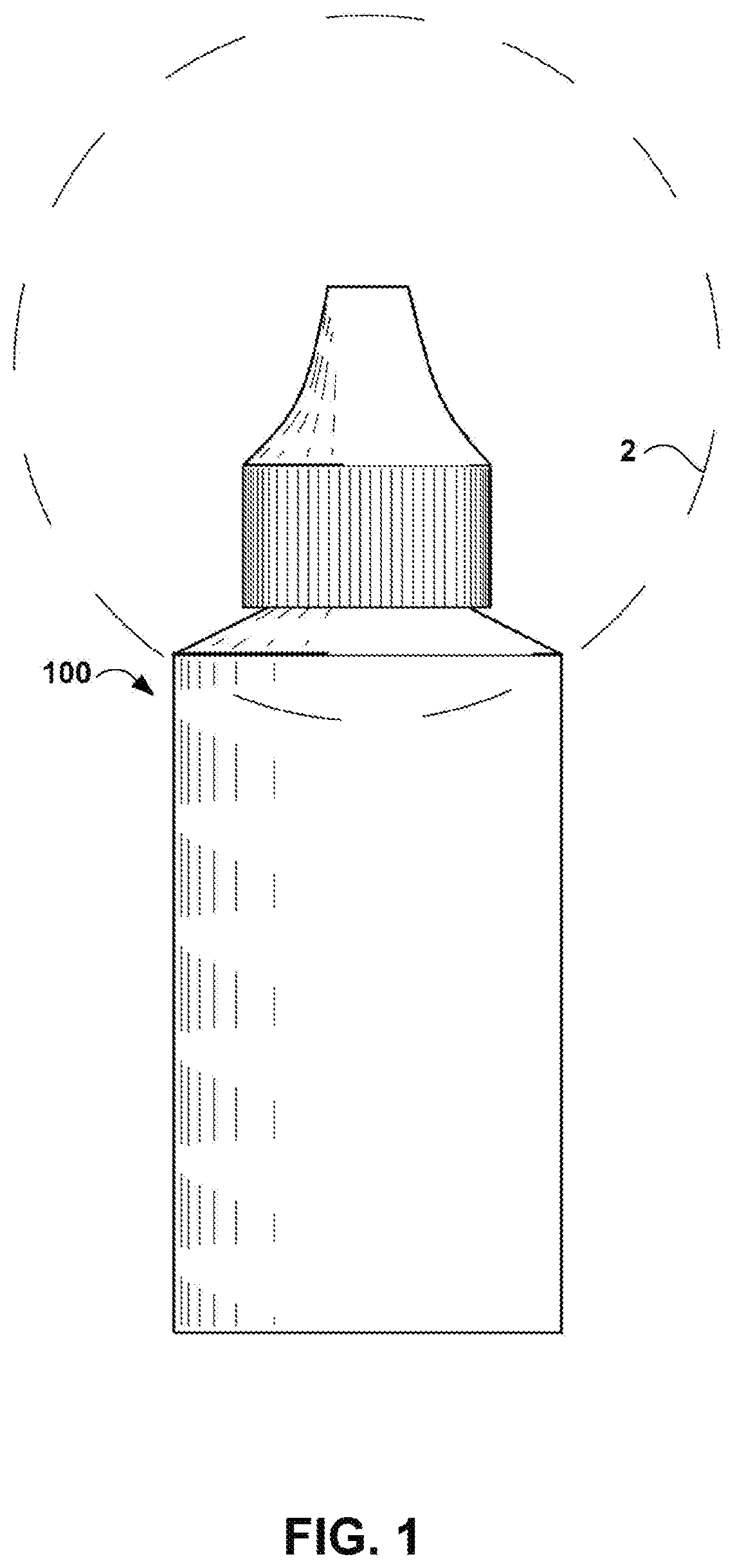
[0017]The micro drop adapter is described herein according to multiple implementations. As a convention for orientation, the descriptive directions of up, above, on top of, down, under, below, etc. may be used. One having ordinary skill in the art will understand that a bottle is typically oriented with the base or bottom of the bottle in the lowest position and the tip of the bottle will be positioned in the highest position. Therefore, terms such as up, above, on top of, etc. will refer to a relative position that is further from the base or bottom of the bottle. And similarly, terms such as down, under, below, etc. will refer to a relative position that is closer to the base or bottom of the bottle.

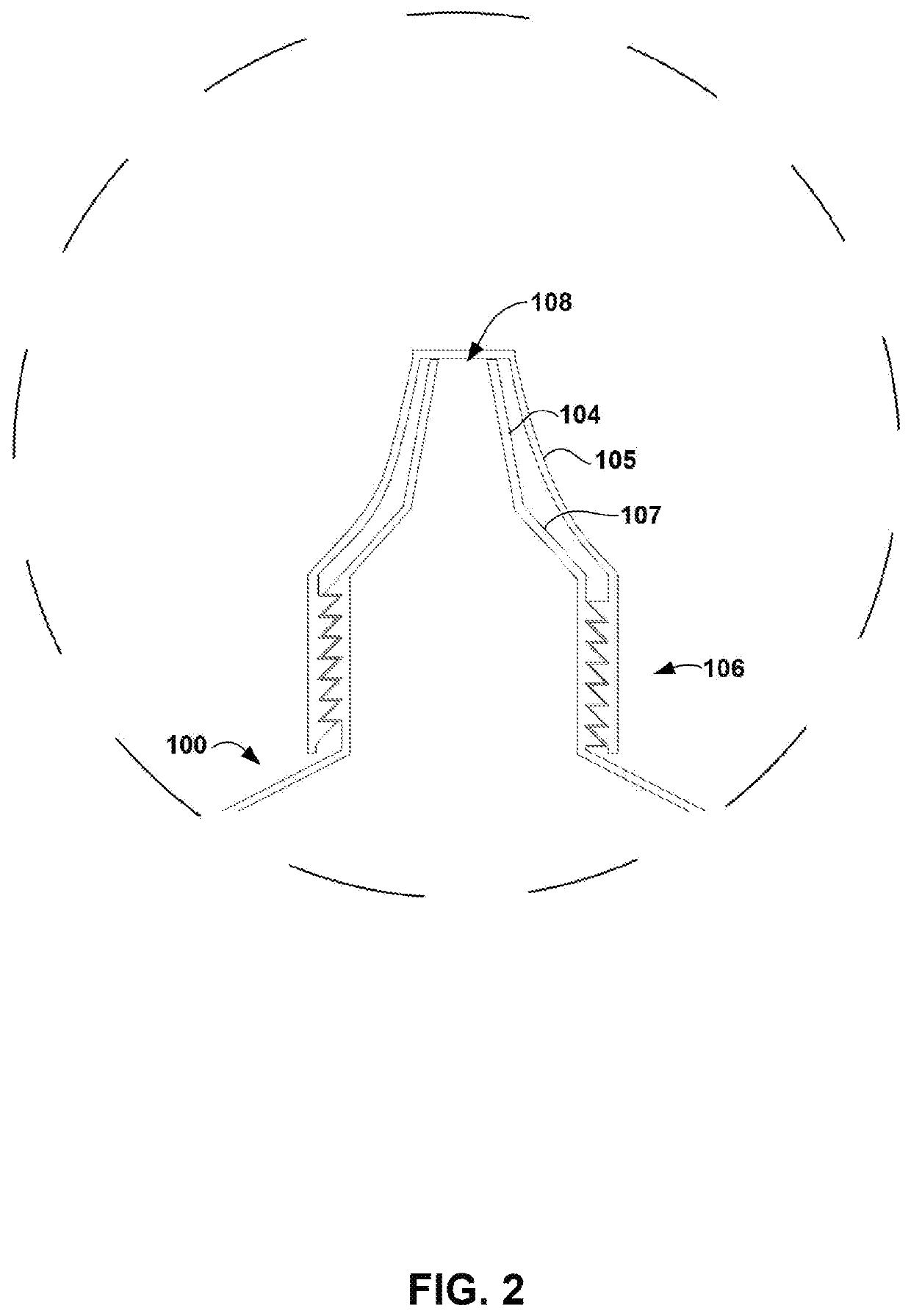
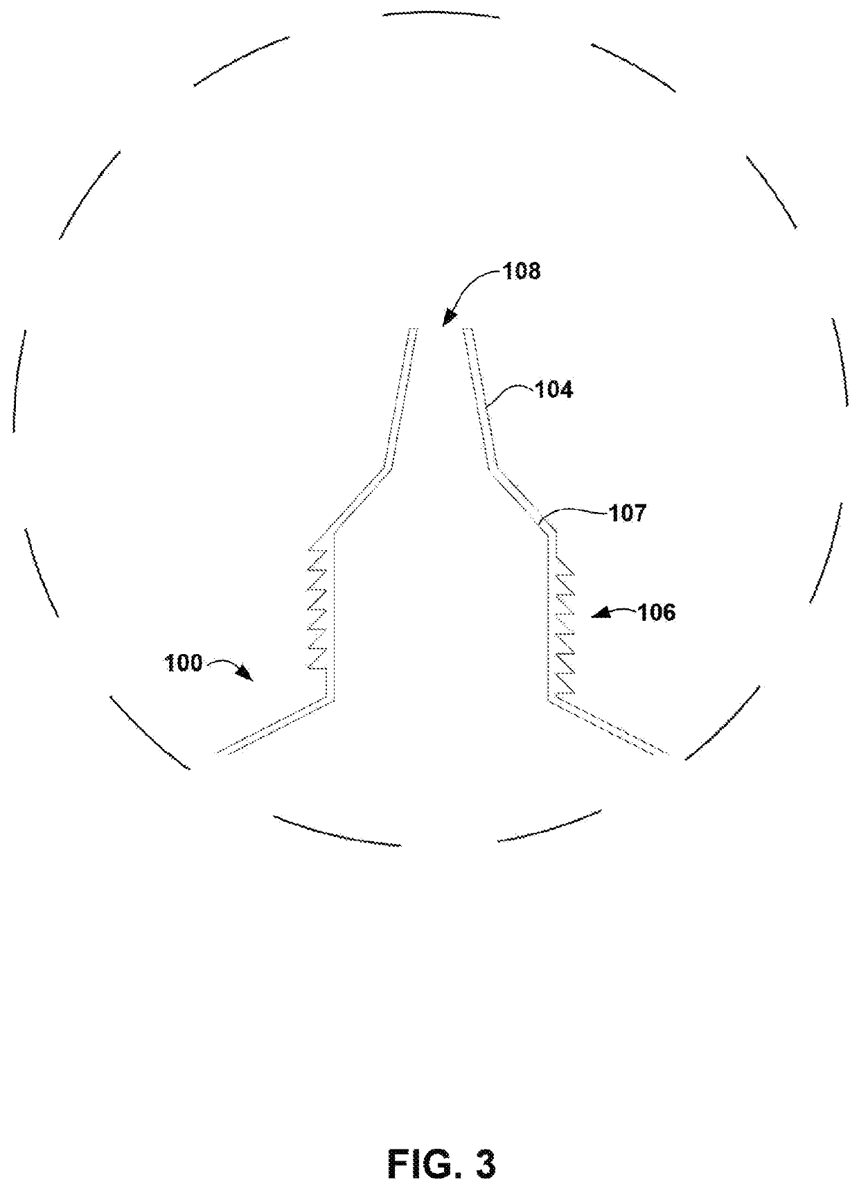
[0018]The typical prior art dropper bottle 100, shortened to “the bottle 100,” is well understood in the art, but essentially consists of a circular or oval shaped base, a sidewall, and a top dispensing portion. See FIG. 1-3. The bottle 100 is capable of dispensing drops having approxi...


PUM


Abstract

The invention described herein concerns a micro drop adapter that is adapted to engage with dropper bottles. The micro drop adapter engages with and surrounds the original tip of the bottle. The micro drop adapter comprises at least one inner tube that is urged against the original tip of the bottle forming a seal and a channel in fluid connection with the bottle. The micro drop adapter comprises an adapter tip that dispenses micro drops, which are drops having a volume of less than approximately 50 microliters. The micro drop adapter further comprises a cap.

Description

CROSS-REFERENCE TO RELATED APPLICATIONS[0001]This application does not claim the benefit of another application.STATEMENT REGARDING FEDERALLY SPONSORED RESEARCH OR DEVELOPMENT[0002]Not ApplicableREFERENCE TO SEQUENCE LISTING, A TABLE, OR A COMPUTER PROGRAM LISTING COMPACT DISC APPENDIX[0003]Not ApplicableBACKGROUND[0004]An eye drop bottle typically dispenses about 50 microliters per drop, which is about twice the volume the eye can hold. As early as 1992, certain researchers advocated for the use of a “micro drop” in eye drop bottles. The proposed micro drop would consist of drop volumes of about 16 microliters, since the research indicated that the medicinal efficacy was not affected while patients experienced fewer side effects. For purposes of the present disclosure, a micro drop will be understood to be any drop having less than the typical 50 microliters volume. Additionally, it was found that patients preferred the micro drops. However, to date the use of micro drops has never...

Claims


Application Information

Patent Timeline
Patent Type & Authority Patents(United States)
IPC IPC(8): A61F9/00B65D47/18
CPCA61F9/0008B65D47/18
Inventor ENEMARK, PAUL
Owner NANODROPPER INC
Why Eureka
Try Eureka