Wearable hip joint-action detectors

a detector and hip joint technology, applied in the field of wearable hip joint action detectors, can solve the problems of inability to detect other types of physical activity, inability to reliably distinguish between sitting and standing, and high risk of heart disease and other causes

Active Publication Date: 2021-03-30
ENBIOMEDIC
View PDF9 Cites 1 Cited by
  • Summary
  • Abstract
  • Description
  • Claims
  • Application Information

AI Technical Summary

Benefits of technology

[0012]In accordance with a first embodiment of a wearable joint-action sensor, the sensor comprises a capacitive proximity sensor that is worn on the right waist of the torso of a user, above the right thigh of the right upper leg, for detecting flexion and extension of the right hip joint, without requiring the user to attach a sensor to the right thigh. The capacitive proximity sensor detects the amount of separation between the capacitive proximity sensor and the right abdomen of the torso above the right thigh as the right hip joint is flexed or extended. Based on the amount of separation and its rate of change, the wearable joint-action sensor can detect actions of the right hip joint of the user, such as walking, running, sitting, and standing.
[0018]In accordance with a seventh embodiment of a wearable joint-action sensor, the sensor comprises a capacitive proximity sensor that is worn on top of two adjacent sections of the upper spinal column of a user. The capacitive proximity sensor detects the amount of separation between the capacitive proximity sensor and a region comprising the two adjacent sections of the upper spinal column as the upper spinal column is flexed or extended. Based on the separation and its rate of change, the wearable joint-action sensor can detect actions of the upper spinal column, such as flexion and extension. The wearable joint-action sensor can inform the user of poor posture because of excessive flexion of the upper spinal column by activating a reminder to produce vibration, sound, voice, display, or light.

Problems solved by technology

In addition, a recent study shows that prolonged sitting is linked to higher risk of death from heart disease and other causes, even if a person gets regular exercise.
A modern pedometer typically incorporates an accelerometer to detect body vibrations for counting steps as a user walks or runs, but cannot detect other types of physical activity.
For example, we have found that a pedometer cannot reliably distinguish between sitting and standing, because a user is stationary in both cases.
Although this pedometer can detect steps reliably without suffering interference from body vibrations not related to walking or running, it still cannot detect whether a user is sitting, standing, or performing any type of physical activity other than walking and running.
Furthermore, we have found that this type of step sensor would not be very reliable and durable because of wear and tear of the mechanical parts after repeated use.
Although this method can detect many types of physical activity performed by a user, physically attaching a sensor of rotation angles to two body segments connected by a joint is inconvenient and cumbersome.
Although this method can detect any physical activity, the relatively complex system requires placing a sensor module on each of the two body segments linked by a joint for determining the degree of flexion of the joint.
The system is too complicated and costly for detecting common physical activities such as walking, running, sitting, and standing, so it is not practical for widespread use.
However, the aforementioned prior-art approaches for monitoring physical activities either do not detect joint actions or use complicated devices for detecting joint actions.
(a) Accelerometer-based pedometers might mistakenly count steps when a user's body vibrates.
(b) A current physical-activity monitor, such as a pedometer, worn on the waist, wrist, or foot of a user, can only detect that the user is walking or running, but not any other type of physical activity, such as sitting or standing.
(c) Current joint-action sensors that can detect a user performing a physical activity by sensing the actions of the joints involved in the physical activity are inconvenient, cumbersome, and costly, so they are not practical for widespread use.

Method used


Image

  • Wearable hip joint-action detectors
  • Wearable hip joint-action detectors
  • Wearable hip joint-action detectors

Examples


first embodiment

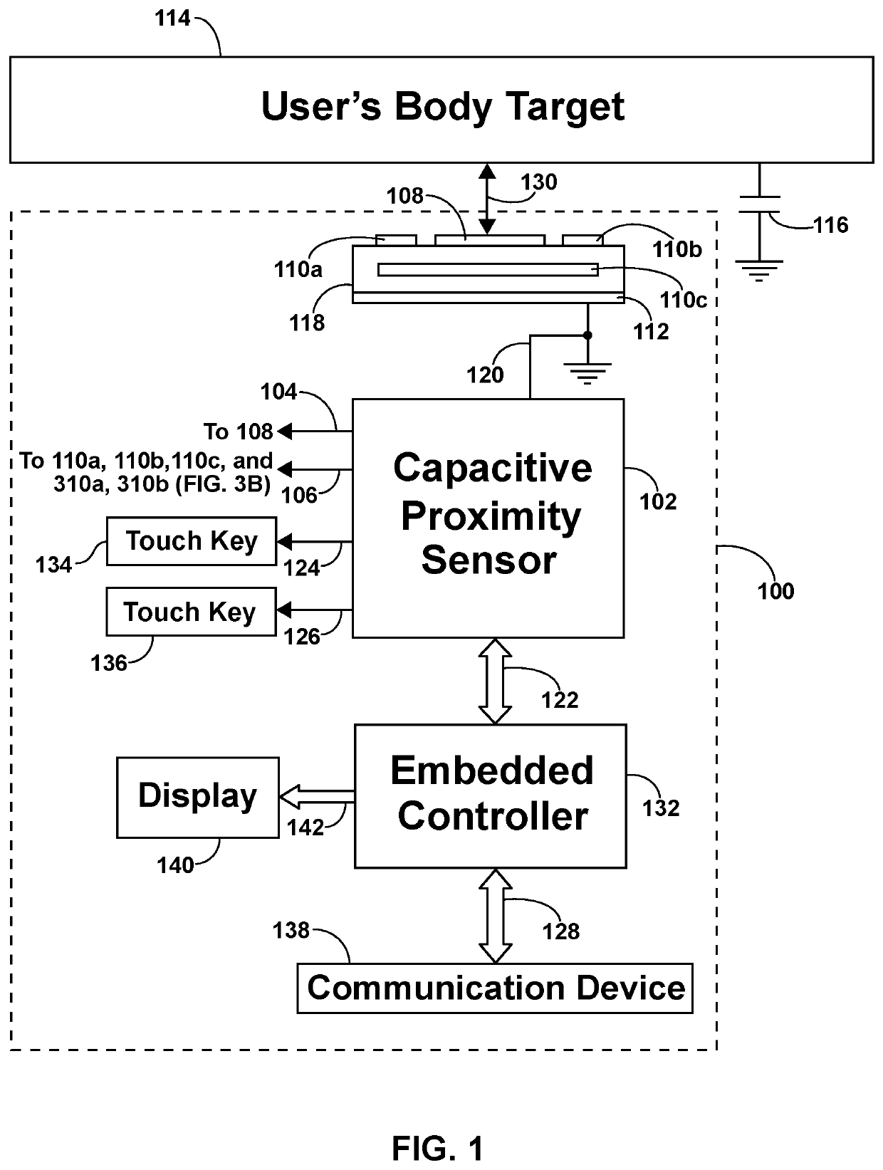
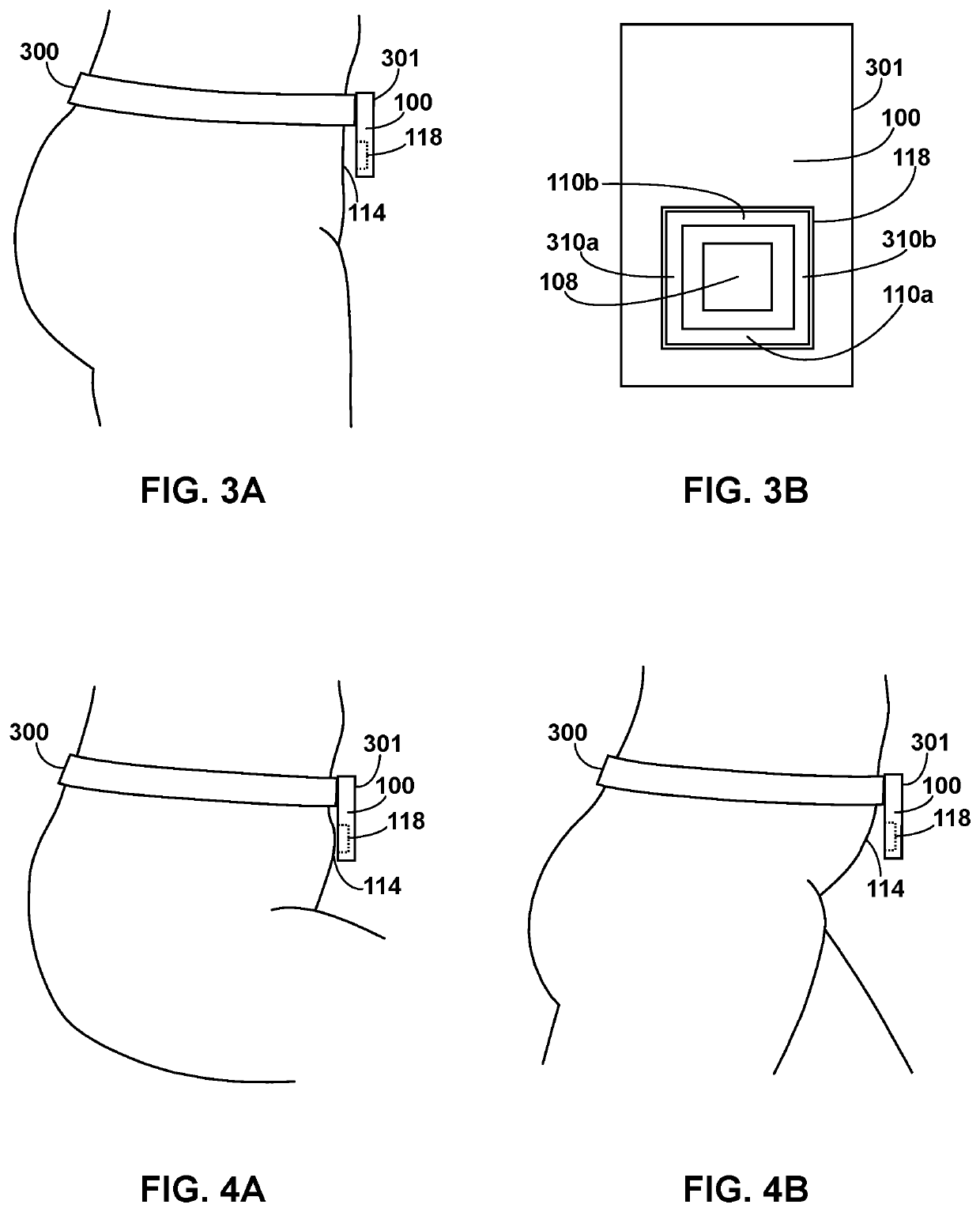
[0080]A first embodiment of the wearable joint-action sensor is illustrated in FIGS. 3A and 3B. FIG. 3A is a side view of wearable joint-action sensor 100 inside a housing 301 worn on the right waist of the torso (the torso is the first body segment in this embodiment) of a user (a human being in this embodiment) with a waist belt 300 for detecting joint actions, such as flexion and extension, of the right hip joint of the user. Wearable joint-action sensor 100 inside housing 301 incorporates sensing plate 118 (details in FIGS. 1 and 3B), which is illustrated by a dotted outline. The right hip joint links the right abdomen of the torso to the right thigh of the right upper leg (the right upper leg is the second body segment in this embodiment), and sensing pad 108 on sensing plate 118 of wearable joint-action sensor 100 is in the proximity of the first body segment (the right abdomen of the torso above the right thigh) for detecting separation 130 (in FIG. 1) between capacitive prox...

second embodiment

[0093]A second embodiment of the wearable joint-action sensor is illustrated in FIG. 5. FIG. 5 is a side view of wearable joint-action sensor 100 inside a housing 501 worn on the right shoulder of the torso (the torso is the first body segment in this embodiment) of a user (a human being in this embodiment), on a shoulder pad 500 with a shoulder strap 502, for detecting actions, such as abduction and adduction, of the right shoulder joint of the user. Wearable joint-action sensor100 inside housing 501 incorporates sensing plate 118, which is illustrated by a dotted outline. Sensing plate 118 of wearable joint-action sensor 100 is in the proximity of the user's right shoulder of the torso and the top of the right upper arm (the right upper arm is the second body segment in this embodiment), and both the right shoulder of the torso and the top of the right upper arm (i.e. the region comprising both the first and second body segments) serve as user's body target 114 for sensing plate 1...

third embodiment

[0099]A third embodiment of the wearable joint-action sensor is illustrated in FIG. 7. FIG. 7 is a side view of wearable joint-action sensor 100 inside a housing 701 worn on the wrist region of the right forearm (the right forearm is the first body segment in this embodiment) of a user (a human being in this embodiment) with a wristband 700 for detecting joint actions, such as flexion and extension, of the right wrist joint of the user. Wearable joint-action sensor 100 inside housing 701 incorporates sensing plate 118, which is illustrated by a dotted outline. Sensing plate 118 of wearable joint-action sensor 100 is in the proximity of the wrist region of the right hand (the right hand is the second body segment in this embodiment) and the wrist region of the right forearm. The right wrist joint links the wrist region of the right forearm to the wrist region of the right hand, and both the wrist region of the right forearm and the wrist region of the right hand (i.e. the region comp...


PUM


Abstract

An activity detector worn on or in the vicinity of the waist detects hip-joint actions of the user, by using a proximity sensor in the activity detector to sense the separation between the activity detector housing and a body target linked by the hip joint. For example, when the housing of an activity detector adjacent to the lower abdomen incorporates one or more sensing plates of a capacitive proximity sensor, flexion, extension, abduction, or adduction of the hip joint can be detected as the separation between the sensing plates and the lower abdomen changes. Besides the lower abdomen, alternative body targets include the thigh, buttocks, etc. Besides capacitive proximity sensors, alternative proximity sensors include active infrared proximity sensors, imaging sensors, etc. The activity detector can also incorporate an accelerometer to obtain additional movement and orientation data, which can be combined with the separation data to detect more complex activities.

Description

CROSS-REFERENCE TO RELATED APPLICATIONS[0001]This application claims the benefit of provisional application Ser. No. 62 / 102,494, filed 2015 Jan. 12 by the present inventors.BACKGROUNDPrior Art[0002]Physical activity is one of the most important factors in reducing the risk of obesity, cardiovascular disease, diabetes, metabolic syndrome, colon cancer, breast cancer, and depression. In addition, a recent study shows that prolonged sitting is linked to higher risk of death from heart disease and other causes, even if a person gets regular exercise. Pedometers are commonly used to monitor physical activity, and are usually worn on the waist, wrist, or foot of a user. A modern pedometer typically incorporates an accelerometer to detect body vibrations for counting steps as a user walks or runs, but cannot detect other types of physical activity. For example, we have found that a pedometer cannot reliably distinguish between sitting and standing, because a user is stationary in both case...

Claims


Application Information

Patent Timeline
Patent Type & Authority Patents(United States)
IPC IPC(8): A61B5/00A61B5/11
CPCA61B5/4528A61B5/1116A61B5/1118A61B5/1128A61B5/6823A61B5/6826A61B2562/0219A61B2562/0257
Inventor YEUNG, KING-WAH WALTERYEUNG, WEI-WEI VIVIAN
Owner ENBIOMEDIC
Why Eureka
Try Eureka