
Dynamic adjustment of charging voltage supplied from a first device to a second device

a charging voltage and dynamic adjustment technology, applied in the direction of charging attachment/accumulator, battery overheating protection, safety/protection circuit, etc., can solve the problems of discomfort for users, loss of linear charging, shortening the life of the batteries in both the case and the earbuds, etc., to improve power delivery efficiency, low input dropout voltage, and small linear charger

Active Publication Date: 2021-06-01
GOOGLE LLC
View PDF23 Cites 6 Cited by
  • Summary
  • Abstract
  • Description
  • Claims
  • Application Information

AI Technical Summary

Benefits of technology

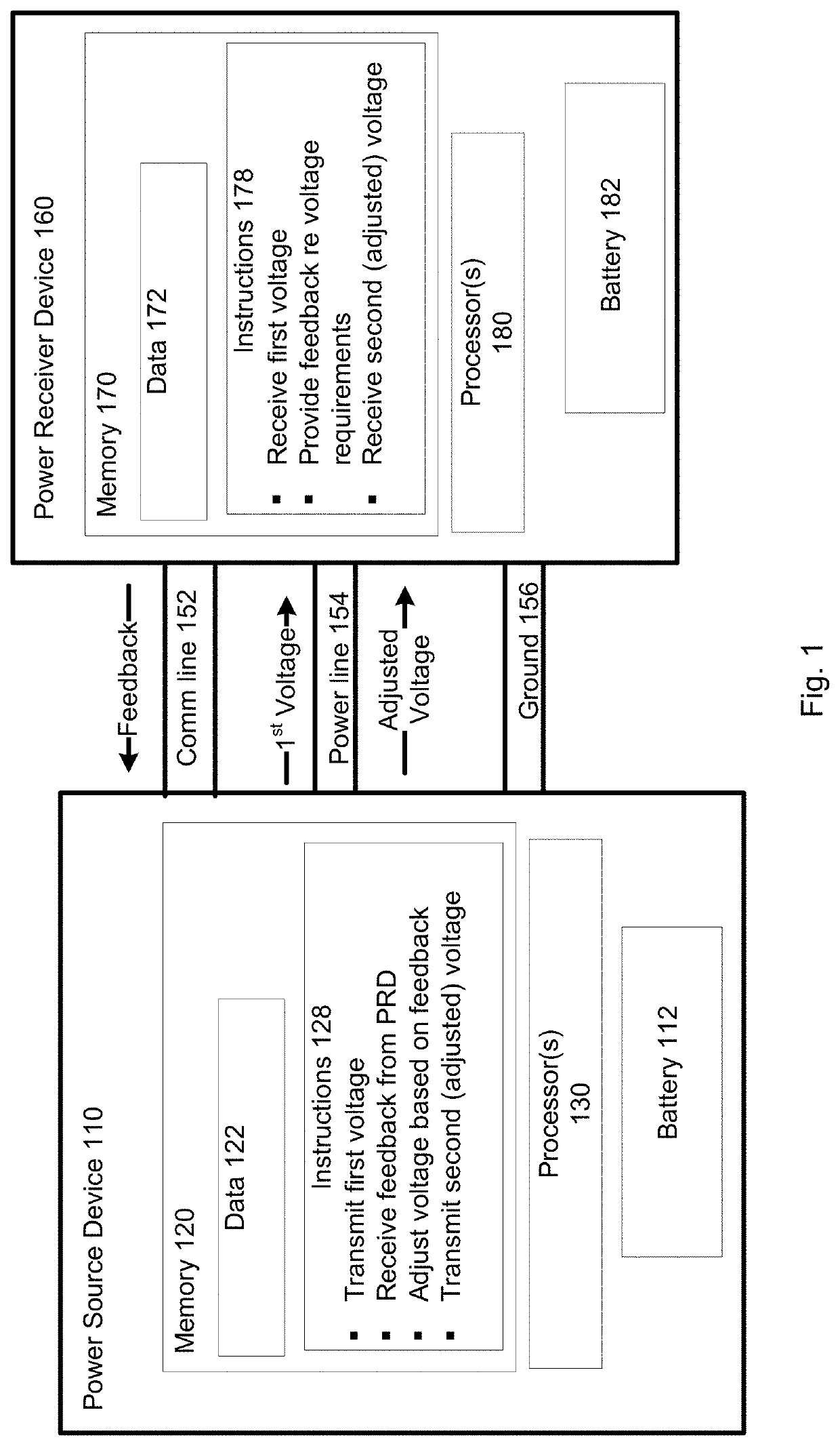
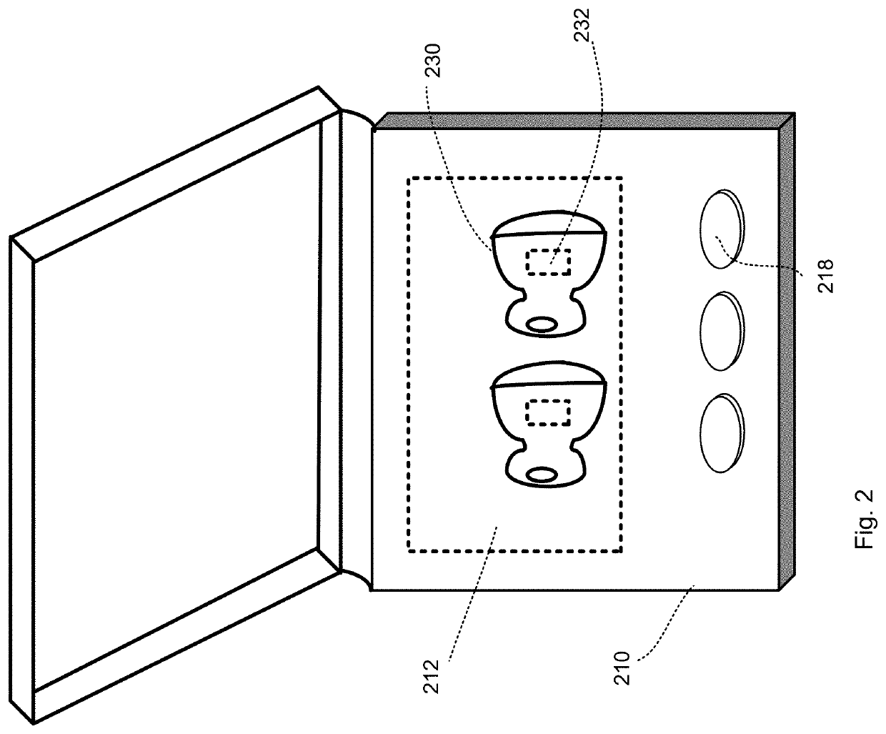
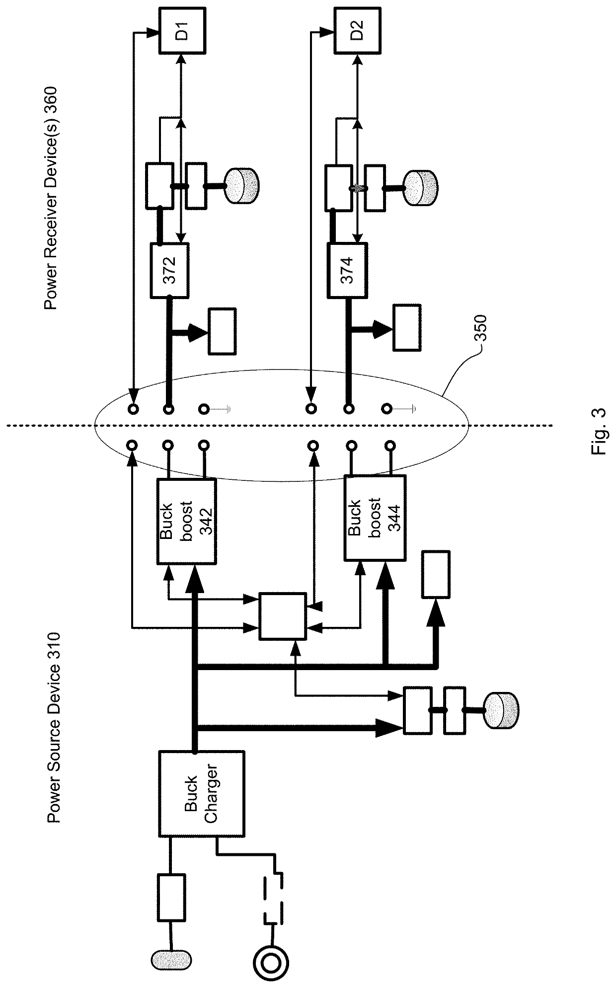
[0004]A new system and method for delivering power from a case to earbuds or other wearable audio devices is described herein. The wearable audio devices can have a small linear charger, with low input dropout voltage. The case has two channel-adjustable output voltages. A communication line between the wearable audio device and the case allows the wearable device to report charging status. By way of example only, the wearable audio device may report to the case that an input to its charger is too low, and needs to increase by 10 mV. The case will dynamically adjust the output voltage, to just meet the minimum voltage requirement at buds. Such a design provides a significant improvement in power delivery efficiency.

Problems solved by technology

Linear charging is often used to transfer power from the case to such smaller earbuds, but linear charging is very lossy.
The extra heat generation can also shorten the life of the batteries in both the case and the earbuds, and cause discomfort to users.

Method used


Image

  • Dynamic adjustment of charging voltage supplied from a first device to a second device
  • Dynamic adjustment of charging voltage supplied from a first device to a second device
  • Dynamic adjustment of charging voltage supplied from a first device to a second device

Examples


Embodiment Construction

[0019]The present disclosure provides for a power source device adapted to supply an adjustable voltage to a power receiver device to charge a battery of the power receiver device. The amount of voltage supplied may be adjusted based on requirements of the power receiver device. For example, the adjustment may be based on feedback from the power receiver device. In one example, the power receiver device may specify an amount of increase or decrease in voltage required. In another example, the power receiver device may communicate its voltage requirements, and allow the power source device to determine how the supplied voltage should be adjusted. Voltage requirements of the power receiver device may change, for example, based on temperature, battery voltage, or other conditions. For example, the power receiver device takes the input voltage, and charges its internal battery. The battery may have one or more different charging algorithms, such as at temperatures between 0-15C, only ch...


PUM


Abstract

A first electronic device, electronically coupled to a second device for supplying a charge to the second electronic device, tracks the voltage requirements of the second device and dynamically adjusts its output voltage upwards or downwards to match such requirements. The second electronic device may provide feedback to the first electronic device through a feedback loop. The feedback may include an indication of the voltage requirements and / or instructions for adjusting the voltage output of the first electronic device. The second device may be, for example, a wearable audio device, while the first device is a case for the wearable audio device.

Description

BACKGROUND[0001]A typical hearable device is designed with a case and two earbuds. The case provides protection when the earbuds are not in use. The case may also charge the earbuds by transferring power from its internal battery to a battery of the earbuds.[0002]Smaller earbud designs typically include a battery under 50 mAh. Linear charging is often used to transfer power from the case to such smaller earbuds, but linear charging is very lossy. A linear charger requires a voltage higher than the battery to be charged, and regulates a voltage drop between a source and a load by inserting a resistive device to keep load voltage stable. The amount of loss is equal to the voltage drop multiplied by the current. The system power delivery efficiency is typically under 80%.[0003]If the charging efficiency is low, a bigger battery is needed in the case. The extra heat generation can also shorten the life of the batteries in both the case and the earbuds, and cause discomfort to users. Acc...

Claims


Application Information

Patent Timeline
Patent Type & Authority Patents(United States)
IPC IPC(8): H02J7/34H04R1/10H02J7/00
CPCH02J7/342H04R1/1016H04R1/1025H04R1/1041H02J7/00034H02J7/0044H02J7/00302H02J7/00309H02J7/007182H02J7/007192H02J2207/20H04R2420/07H02J7/007194
Inventor DING, YAOHERMOSILLO, TREVORSHMUKLER, MAKSIMLEUNG, CHI KIN BENJAMIN
Owner GOOGLE LLC
Learn More