Cutting apparatus

a cutting apparatus and cutting head technology, applied in the direction of tunnels, mining structures, slitting machines, etc., can solve the problems of fatigue and wear of cutters, the cutting head arrangement is not optimised, and the cutting head on these devices is not optimised to cut hard rock having a strength, etc., to achieve optimised cutting geometry, optimise cutting strength, and optimise cutting

Active Publication Date: 2021-06-29
SANDVIK INTELLECTUAL PROPERTY AB
View PDF19 Cites 0 Cited by
  • Summary
  • Abstract
  • Description
  • Claims
  • Application Information

AI Technical Summary

Benefits of technology

[0007]It is an objective of the present invention to provide cutting apparatus suitable to form tunnels and subterranean roadways being specifically configured to cut hard rock, say beyond 120 MPa, in a controlled and reliable manner, that is, apparatus capable of mine development work. It is a further objective to provide a cutting apparatus capable of creating a tunnel with a variable cross sectional area within a maximum and a minimum cutting range. It is a further objective to provide cutting (excavator) apparatus operable in an ‘undercutting’ mode according to a two stage cutting action. It is a further objective to provide a cutter that has an optimised cutting geometry for the cutting apparatus. It is a further object to provide a cutter that has an optimised geometry for balancing cutter strength and reducing cutter wear.

Problems solved by technology

However, conventional cutting machines are not optimised to cut hard rock having a strength typically beyond 120 MPa whilst creating a tunnel or subterranean cavity safely and reliably of desired cross sectional configuration.
WO2016 / 055087 describes a type of machine that is addresses some of these problems, however the inventors have determined that the arrangement of the cutting heads on these devices is not optimised.
Furthermore since there are a high number of load cycles this tends to fatigue and wear the cutters more than is necessary.

Method used


Image

  • Cutting apparatus
  • Cutting apparatus
  • Cutting apparatus

Examples


Embodiment Construction

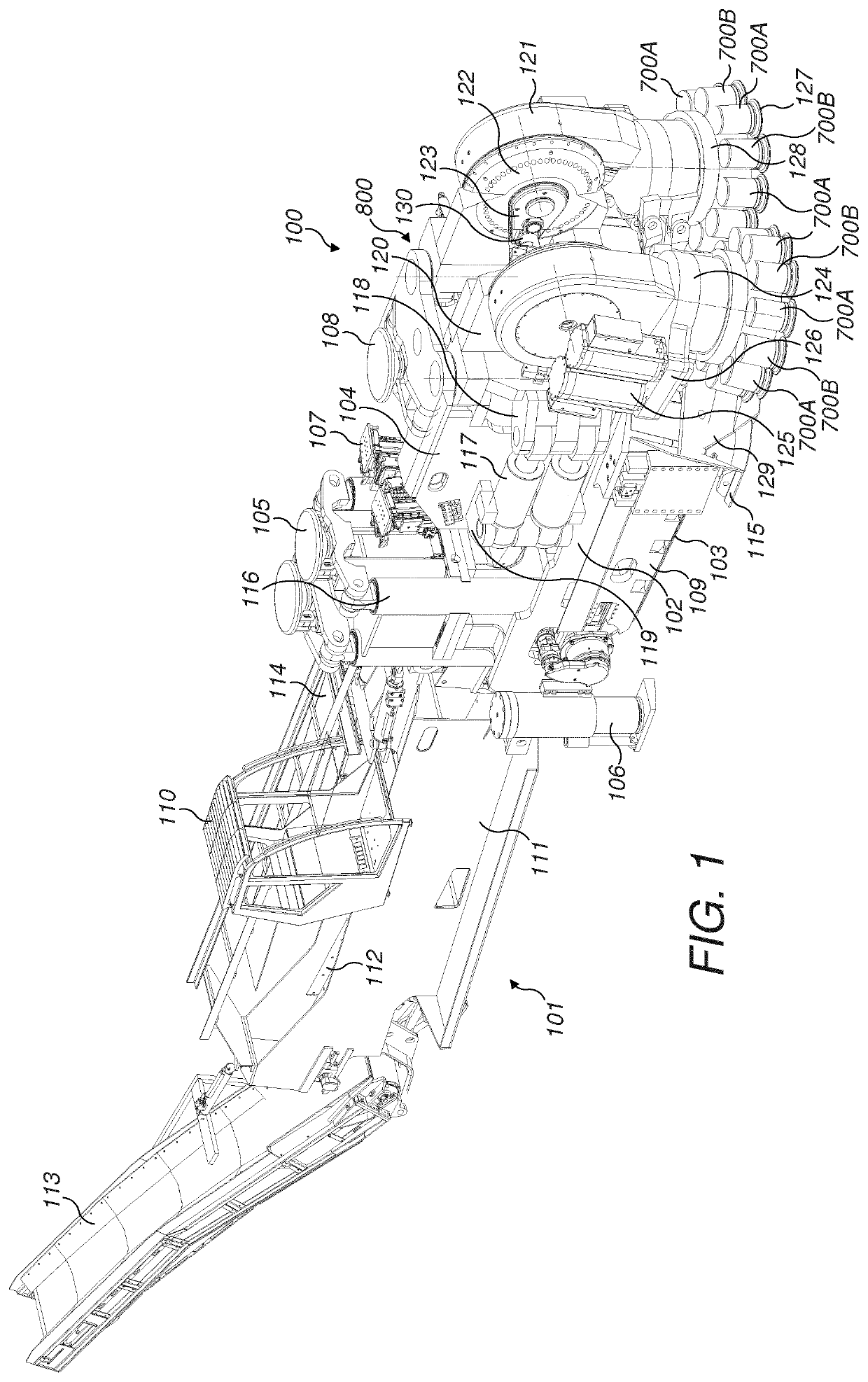
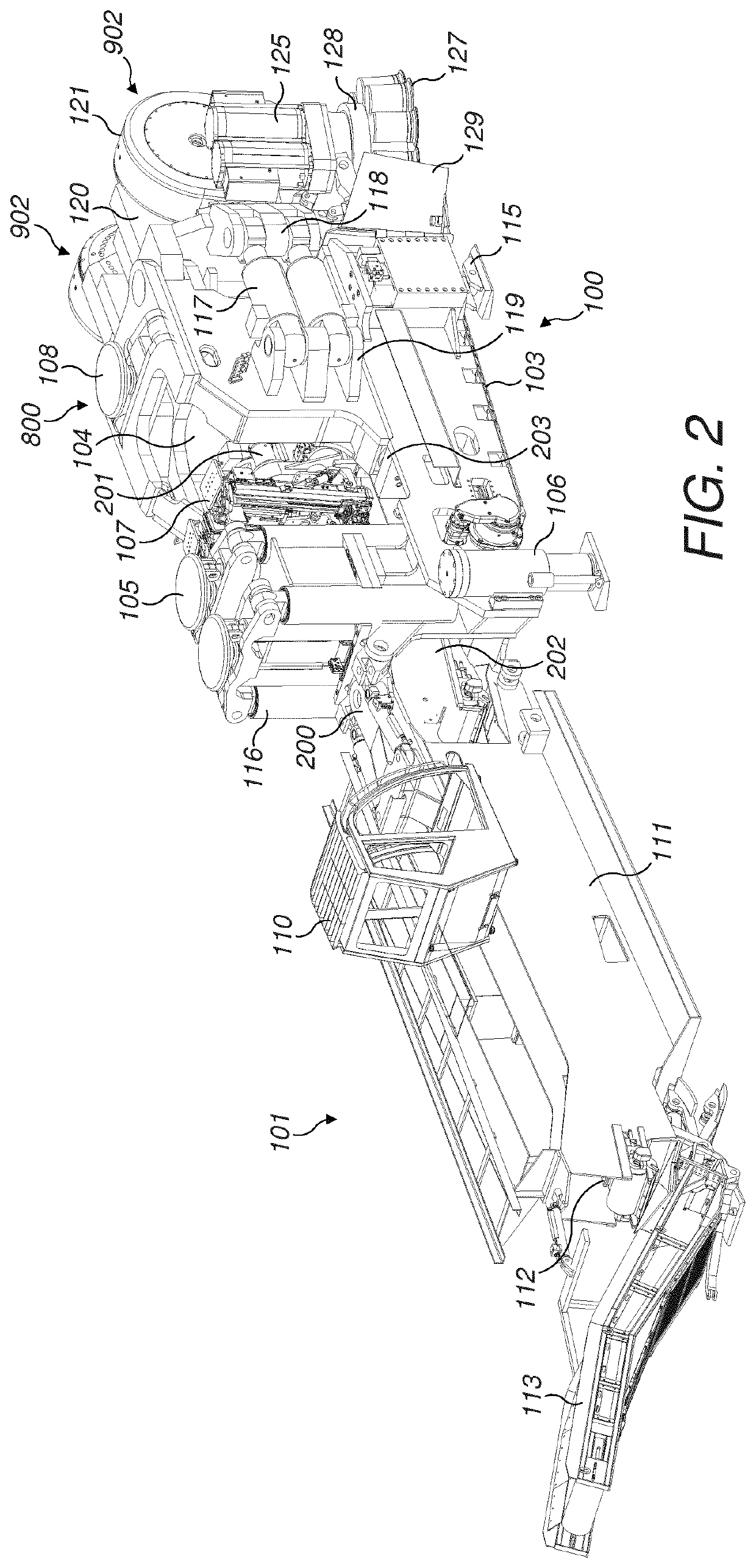
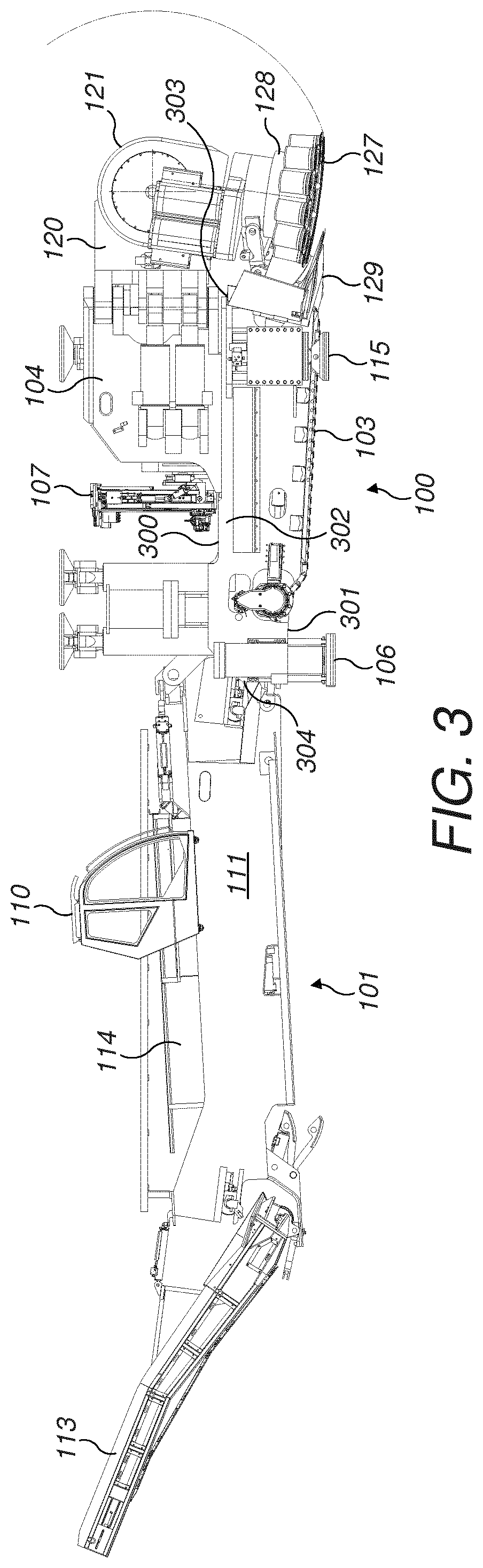
[0061]Referring to FIG. 1, cutting apparatus 100 comprises a support structure 800 mounting a plurality of cutting components configured to cut into a rock or mineral face 1000 to create tunnels or subterranean roadways. Apparatus 100 is configured specifically for operation in an undercutting mode in which a plurality of rotatable roller cutters 127A, 127B may be forced into the rock to create a groove or channel and then to be pivoted vertically upward so as to overcome the reduced tensile force immediately above the groove or channel and break the rock. Accordingly, the present cutting apparatus is optimised for forward advancement into the rock or mineral utilising less force and energy typically required for conventional compression type cutters that utilise cutting bits or picks mounted at rotatable heads. However, the present apparatus may be configured with different types of cutting head to those described herein including in particular pick or bit type cutting heads in whi...


PUM


Abstract

A cutting head for cutting apparatus suitable for creating tunnels or subterranean roadways and the like. The cutting head includes a rotatable cutting head body and a plurality of cutting units mounted thereon. The cutting units include at least first and second different types of cutting units. The first type of cutting unit has a first rotatable cutter having a first disc body and a first arrangement of buttons for abrading rock. The first buttons are mounted in a radially peripheral portion of the disc body and protrude outwardly therefrom. The second type of cutting unit has a second rotatable cutter having a second disc body and a second arrangement of buttons. The second buttons are mounted in a radially peripheral portion of the disc body and protrude outwardly therefrom. The different types of cutting units differ from one another by at least the arrangements of their buttons.

Description

RELATED APPLICATION DATA[0001]This application is a § 371 National Stage Application of PCT International Application No. PCT / EP2018 / 058273 filed Mar. 30, 2018 with priority to EP 17166804.9 filed Apr. 18, 2017.FIELD OF INVENTION[0002]The present invention relates to rock cutting apparatus suitable for creating tunnels or subterranean roadways and in particular, although not exclusively, to undercutting apparatus in which a plurality of rotating heads are capable of being slewed laterally outward and raised in the upward and downward direction during forward cutting.BACKGROUND ART[0003]A variety of different types of excavation machines have been developed for cutting drifts, tunnels, subterranean roadways and the like in which a rotatable head is mounted on an arm that is in turn movably mounted at a main frame so as to create a desired tunnel cross sectional profile. WO2012 / 156841, WO 2012 / 156842, WO 2010 / 050872, WO 2012 / 156884, WO2011 / 093777, DE 20 2111 050 143 U1 all described a...

Claims


Application Information

Patent Timeline
Patent Type & Authority Patents(United States)
IPC IPC(8): E21D9/10E21C27/12
CPCE21D9/104E21C27/124E21D9/102
Inventor GARCIA, LUISSTABER, GUENTHER
Owner SANDVIK INTELLECTUAL PROPERTY AB
Why Eureka
Try Eureka