Compressed air nailer with automatic operating mode and a placing sensor

a technology of automatic operation and placing sensor, which is applied in the direction of nails, nailing tools, fastening means, etc., can solve the problems of increased injury risk, increased risk of injury, and unintentional contact triggers, so as to achieve the effect of safe operation of automatic operating mod

Active Publication Date: 2021-11-09
BEA GMBH
View PDF12 Cites 0 Cited by
  • Summary
  • Abstract
  • Description
  • Claims
  • Application Information

AI Technical Summary

Benefits of technology

[0012]These difficulties are overcome by the particular embodiment of the triggering apparatus with an intermediate position: In the automatic operating mode with the trigger actuated, the control valve remains actuated until the placing sensor is displaced starting from the first, fully actuated position, in which it is located when the compressed air nailer is placed onto a workpiece, along the adjustment path into an intermediate position. The intermediate position has a specified distance from the first position. The actuation of the control valve and therefore of the automatic operating mode ends only when the compressed air nailer is removed so far from the workpiece that the placing sensor reaches the intermediate position. In an embodiment, the specified distance is chosen so that it is generally not exceeded by slight, more or less unavoidable jumps of the compressed air nailer. This enables trouble-free operation in the automatic operating mode.
[0022]In one embodiment, the force transmission element is a rocker, one end of which is mounted rotatably on the trigger and the other end of which has the stop. The rocker can in particular be arranged completely or partially within the trigger. In this manner, a reliable and compact design of the triggering apparatus is achieved.

Problems solved by technology

This contact trigger operating mode, however, is associated with an increased risk of injury if an inattentive user unintentionally actuates the placing sensor when the trigger is actuated—for example, if he accidentally brushes the compressed air nailer against his leg while climbing a ladder.
The possibility of an unintentional contact triggering also presents an increased risk of injury with these devices.

Method used


Image

  • Compressed air nailer with automatic operating mode and a placing sensor
  • Compressed air nailer with automatic operating mode and a placing sensor
  • Compressed air nailer with automatic operating mode and a placing sensor

Examples


Embodiment Construction

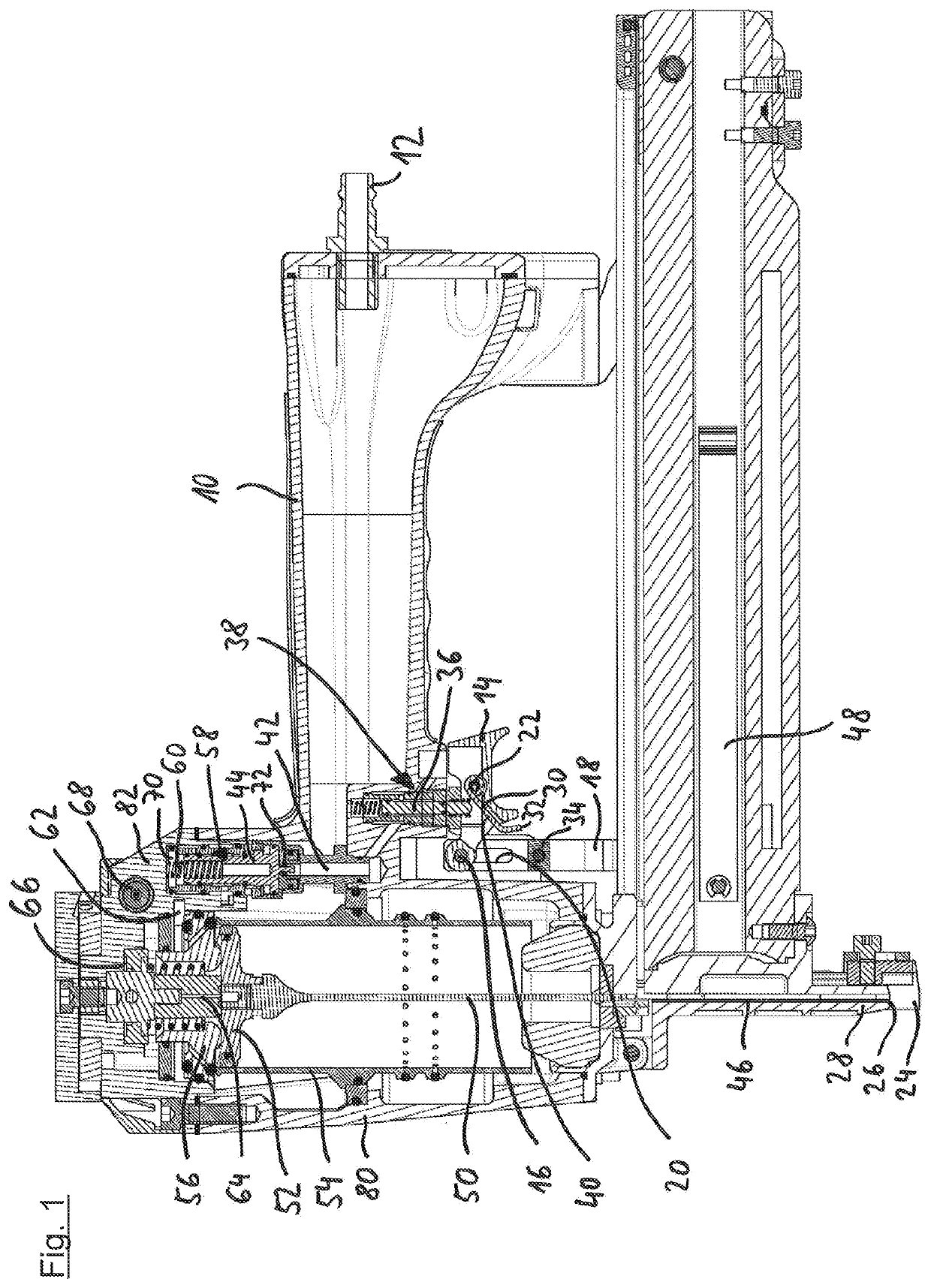
[0033]First, the most important elements of the compressed air nailer are represented, partially in the form of an overview, with reference to FIG. 1. The compressed air nailer has a handle 10, on the rear end of which a central compressed air connection 12 is arranged. The handle 10 is located on a lower housing part 80 that is closed at the top by a housing cap 82.

[0034]The manually actuatable trigger 14 is mounted on the housing of the compressed air nailer in a pivotable manner about a pivot axis 16 and is arranged so that it can be actuated comfortably with the index finger by a user who is holding the compressed air nailer by the handle 10. FIG. 1 shows the trigger 14 in the actuated position.

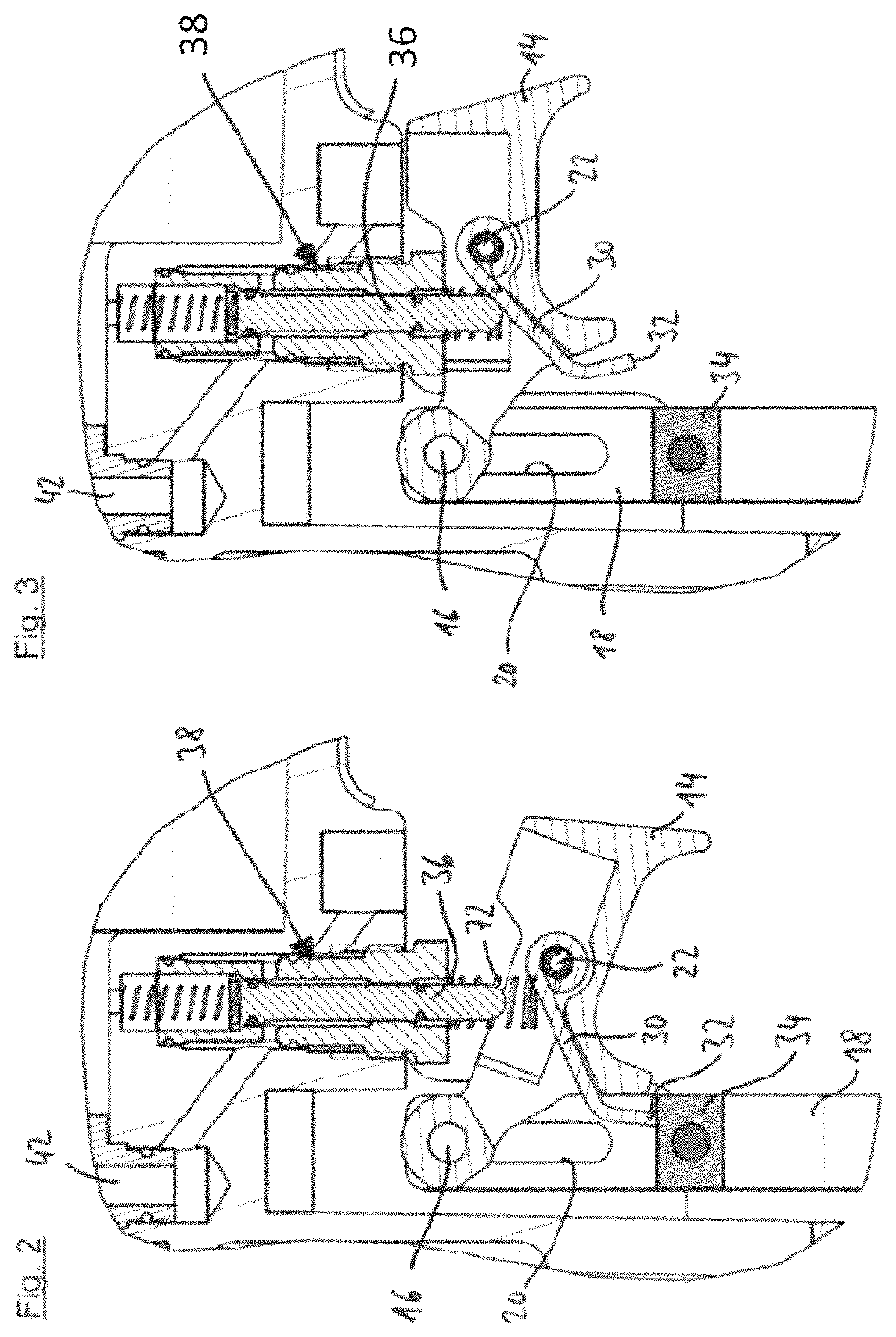
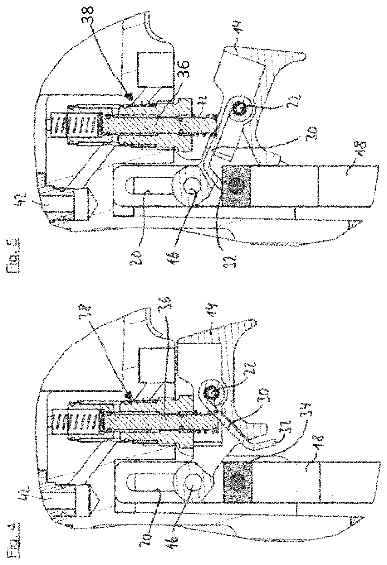
[0035]In the arrangement shown in FIG. 1 with the compressed air nailer removed from a workpiece, the placing sensor 24 projects downwards with its front end over a mouth 26 of an outlet tool 28. This is the fully non-actuated second position of the placing sensor 24. If the compressed ai...


PUM


Abstract

A compressed air nailer comprises a working piston connected to a driving tappet and configured to drive in a fastener and a triggering apparatus. The triggering apparatus comprises a manually actuable trigger, a placing sensor, and a force transmission element configured to interact with the manually actuable trigger and the placing sensor to actuate a control valve and trigger the driving process when the manually actuable trigger and the placing sensor are actuated together. The compressed air nailer is configured to continuously drive in fasteners in an automatic operating mode when the manually actuable trigger and the placing sensor are permanently actuated, and wherein displacing the placing sensor from the second position into the first position does not actuate the control valve when the manually actuable trigger is in an actuated position when the placing sensor is displaced.

Description

CROSS REFERENCE TO RELATED INVENTION[0001]This application is a national stage application pursuant to 35 U.S.C. § 371 of International Application No. PCT / EP2018 / 062459, filed on May 15, 2018, which claims priority to, and benefit of, German Patent Application No. 20 2017 104 073.9, filed Jul. 7, 2017, the entire contents of which are hereby incorporated by reference.BACKGROUND[0002]The invention relates to a compressed air nailer with a working piston that is connected to a driving tappet for driving in a fastener and is supplied with compressed air when a driving process is triggered, and a triggering apparatus that has a manually actuatable trigger, a placing sensor and a force transmission element that works together with the trigger and the placing sensor so that it can actuate a control valve and trigger a driving process when the trigger and the placing sensor are actuated together.[0003]Such compressed air nailers are known from the prior art. The placing sensor is a mechan...

Claims


Application Information

Patent Timeline
Patent Type & Authority Patents(United States)
IPC IPC(8): B25C1/00F16B15/08B25C1/04B25C1/18B25C5/13
CPCB25C1/008F16B15/08B25C1/043B25C1/047B25C1/188B25C5/13
Inventor BAUER, JOACHIM
Owner BEA GMBH
Why Eureka
Try Eureka