Vacuum cleaner nozzle incorporating first suction head and second suction head

A technology of vacuum cleaners and suction ports, which is applied in the directions of vacuum cleaners, suction nozzles, household appliances, etc., can solve the problems such as the inability to provide suction nozzles.

Pending Publication Date: 2022-03-04
SEB SA
View PDF1 Cites 0 Cited by
  • Summary
  • Abstract
  • Description
  • Claims
  • Application Information

AI Technical Summary

Problems solved by technology

[0011] However, the aforementioned suction nozzles do not provide an ergonomic solution f

Method used


Image

  • Vacuum cleaner nozzle incorporating first suction head and second suction head
  • Vacuum cleaner nozzle incorporating first suction head and second suction head
  • Vacuum cleaner nozzle incorporating first suction head and second suction head

Examples


Embodiment Construction

[0095] In the following description, the vacuum cleaner nozzle is referred to as a nozzle.

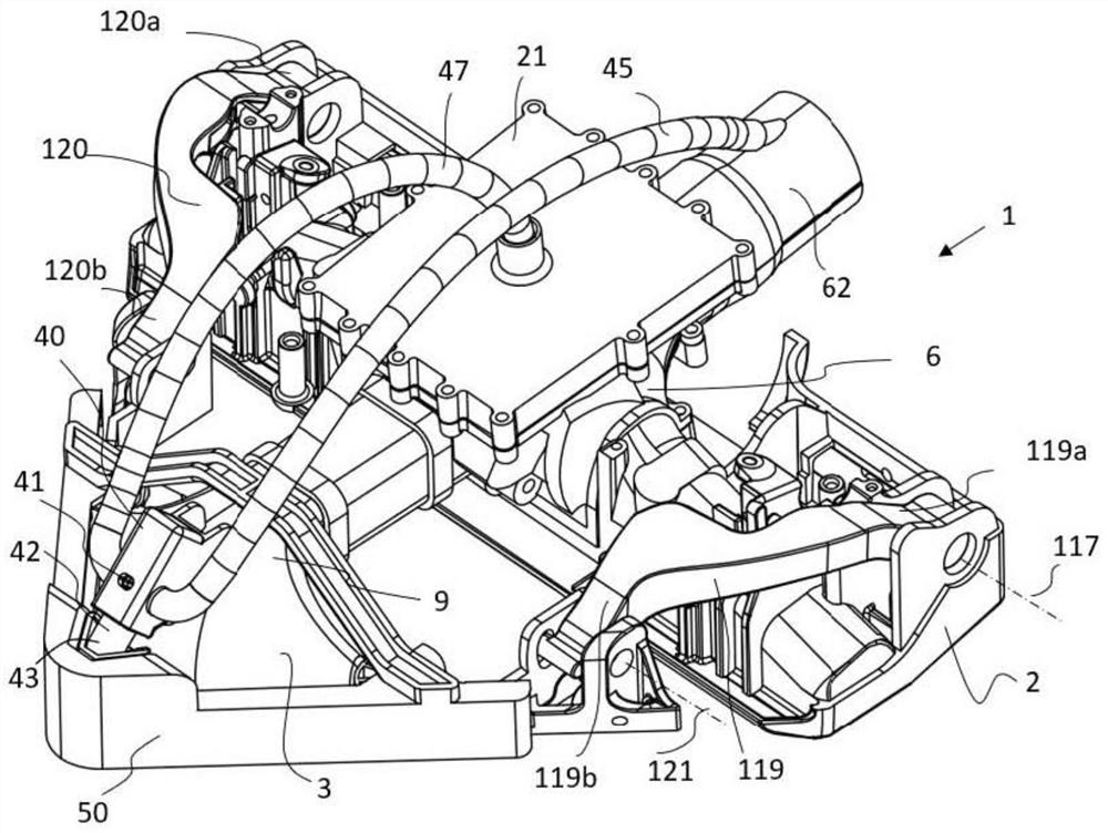
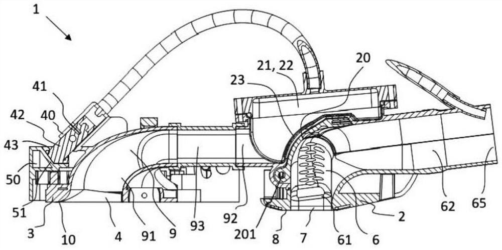
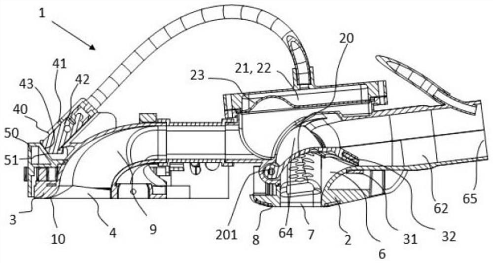
[0096] exist figure 1 In this case, the suction nozzle 1 comprises a first head 2, advantageously constituted by a rectangular head, and a second head 3, advantageously constituted by a triangular head. The second head 3 defines a pointed shape, which includes a suction opening 4, which can also be triangular in shape, so that the suction nozzle 1 can more easily reach the corner of the room or stand along the skirting line. Vacuum surfaces. The suction opening 4 leads to the lower surface 10 of said second head 3 .

[0097] During the process of vacuuming the surface, the suction nozzle 1 is moved back and forth or oppositely. The suction nozzle moves forward when pushed, and moves backward when pulled by, for example, a handle (not shown) integral with a suction pipe (not shown) attached to the suction nozzle 1 . The one or more leading edges of the nozzle define the front of the...


PUM


Abstract

A suction nozzle (1) of a vacuum cleaner designed to move on a surface to be vacuum-cleaned, comprising a first head (2) comprising a first suction conduit (6) pneumatically connected to a first suction opening provided on a lower surface of said first head (2). The suction nozzle (1) of the vacuum cleaner comprises a second head (3) which extends the first head (2) forwards and comprises a second suction port arranged on the lower surface of the second head (3). The suction nozzle (1) of the vacuum cleaner comprises a second suction conduit (9) which extends at least partially into the second head (3) and is pneumatically connected to the second suction opening. The suction nozzle (1) of the vacuum cleaner comprises at least one distributor element allowing a change in suction distribution between a first suction opening and a second suction opening, where the distributor element can be in at least a first distribution position in which the distributor element allows suction at least through the first suction opening and a second distribution position in which the distributor element allows suction at least through the second suction opening. In the second dispensing position, the dispenser element allows suction at least through the second suction opening. The suction nozzle (1) of the vacuum cleaner further comprises a pneumatic actuator (21) allowing the dispenser element to move between a first dispensing position and a second dispensing position.

Description

technical field [0001] The invention relates to the field of vacuum cleaners, in particular to the design of a suction nozzle of a vacuum cleaner. The suction nozzle is also called a suction head or a suction head, and dust is sucked through the suction nozzle. [0002] The present invention aims to devise a vacuum cleaner nozzle that ensures optimum suction over the entire surface to be vacuumed, even if obstacles may be present. Background technique [0003] Traditionally, canister or broom cleaners include a nozzle consisting of a rectangular or triangular head. [0004] The latest design of the suction nozzle with a rectangular head allows effective dusting of all types of surfaces such as carpets, rugs, smooth floors, parquet floors, etc. The most difficult operation is on carpets. In particular, the use of energy labels in the field of vacuum cleaners has led manufacturers to reduce the power of vacuum cleaner motors, thereby reducing the flow rate of suction air, and...

Claims


Application Information

Patent Timeline
IPC IPC(8): A47L9/02A47L9/00A47L5/12
CPCA47L9/02A47L9/00A47L5/12
Inventor 马修·弗恩多纳西安·弗罗
Owner SEB SA
Why Eureka
Try Eureka